I2C RGB LED Board Development
This board will be a 5 RGB LED expansion board driven by a I²C connection.
This board is going to be developed as a KiCAD demonstration. It will use the AW9523B GPIO Expander I²C device. Videos will be recorded all the way - starting with a blank project, developing the schematics, designing and routing the PCB, exporting production files and finally ordering the boards from JLCPCB. Once we receive the boards, we will test them thoroughly and develop a STM32 library interfacing the board using I²C.
Sponsor
While developing this board during some live streams (linked below) I approached JLCPCB to ask if they wanted to sponsor a run of them and they agreed. IF you are interested, please click on the banner below.
Videos
The PCB development of this board was live streamed in 3 separate streams.
You can watch those live streams here: https://www.youtube.com/playlist?list=PLVfOnriB1RjW1bjvfdfvBH_yly3bV6s8T
Schematics and board setup
Routing and tweaking
Ordering from JLCPCB
Receiving and unboxing
Programming the board
Schematics
The schematics is quite simple. A standard 100 mil header with power supply, I²C and a reset pin (which can be ignored).
I²C is connected with some 1K pull-up resistors to the AW9523. The AW9523 then drives 5 RGB LEDs directly.
PCB
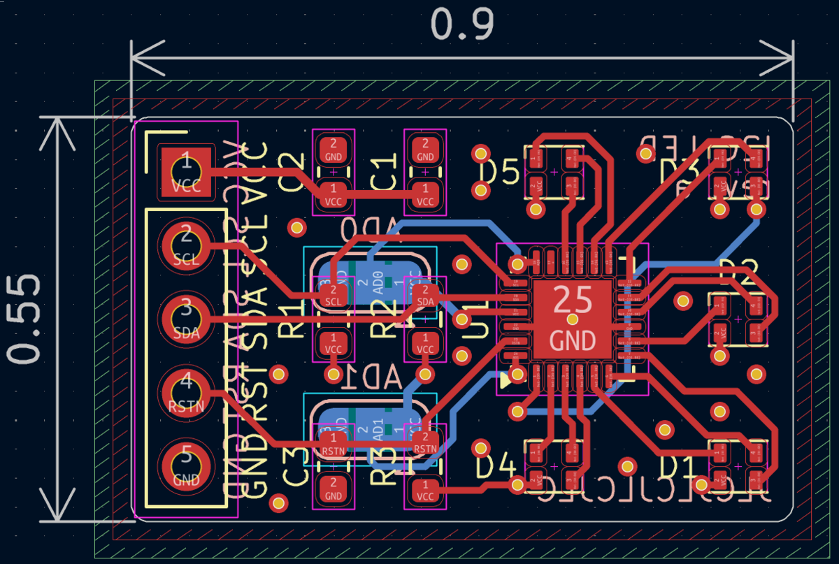
The PCB is quite small and simple and looking like this while working:
A viewer commented that I should have rotated the LEDs. I do beg to differ. The problem is that RGB LEDs - especially at low intensity - the individual R, G and B leds can be seen and if they are rotated at different angles that might look odd. The way I placed them is optimal if you want them to be rotated the same way.
Finished result
To be added
Developing a library
To be added
Gallery
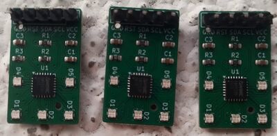
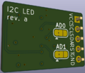
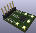
This board was developed primarily as a KiCAD exercise. Here are some renders from KiCAD and some photos of the finished result.


