Difference between revisions of "Green Pill"
| (25 intermediate revisions by the same user not shown) | |||
| Line 1: | Line 1: | ||
| − | [[Category:STM32]][[Category:STM32 Development Board]][[Category:Green Pill]][[Category:STM32 Hardware Development]] | + | [[Category:STM32]][[Category:STM32 Hardware]][[Category:STM32 Development Board]][[Category:STM32 Projects]][[Category:Development Board]][[Category:Green Pill]][[Category:STM32 Hardware Development]][[Category:KiCAD]]{{metadesc|Own design STM32 development board w. stm32f103 mcu roughly equivalent of a blue pill}} |
| − | As mentioned elsewhere, the first STM32 development board I got my hands on was a so-called [[Blue Pill]] and it was a truly horrible experience. I do understand that some of these boards are sold cheaper than the price of a [[STM32F103]] [[MCU]], and it would be perfectly acceptable using clones if this was a well documented fact. Unfortunately, a lot of the vendors use clones which are labelled as genuine [[STM32]] | + | As mentioned elsewhere, the first STM32 development board I got my hands on was a so-called [[Blue Pill]] and it was a truly horrible experience. I do understand that some of these boards are sold cheaper than the price of a [[STM32F103]] [[MCU]], and it would be perfectly acceptable using clones if this was a well documented fact. Unfortunately, a lot of the vendors use clones which are labelled as genuine [[STM32]]s. |
| − | Because of this, and the fact that I wanted to learn how to design electronics around the [[STM32]] [MCU]]s, I decided to roll my own development board. At the time I was doing this, [[JLCPCB]] would only assemble boards with a green soldermask, so I aptly named it the [[Green Pill]]. | + | Because of this, and the fact that I wanted to learn how to design electronics around the [[STM32]] [[MCU]]s, I decided to roll my own development board. At the time I was doing this, [[JLCPCB]] would only assemble boards with a green soldermask, so I aptly named it the [[Green Pill]]. |
| + | |||
| + | == STM32 Tutorial Video == | ||
| + | |||
| + | We are creating tutorial videos which you can watch the video on Youtube: [https://www.youtube.com/watch?v=EZqwBuRpdns https://www.youtube.com/watch?v=EZqwBuRpdns] (full series [[STM32 Getting Started Tutorial Video Series (by STM32World)|here]]). | ||
| + | |||
| + | {{#ev:youtube|EZqwBuRpdns}} | ||
== Schematics design == | == Schematics design == | ||
| Line 7: | Line 13: | ||
The board have gone through a few revisions, but the final version ended up looking like this: | The board have gone through a few revisions, but the final version ended up looking like this: | ||
| − | [[File:Green Pill rev. c.svg| | + | <div class="res-img"> |
| + | [[File:Green Pill rev. c.svg|2200px]] | ||
| + | </div> | ||
This is largely dictated by the availability of parts from [[JLCPCB]]. The USB specification dictates the use of 10uF capacitors as maximum to avoid too large inrush current when it is connected. | This is largely dictated by the availability of parts from [[JLCPCB]]. The USB specification dictates the use of 10uF capacitors as maximum to avoid too large inrush current when it is connected. | ||
| Line 51: | Line 59: | ||
For rev. c a number of changes where made: | For rev. c a number of changes where made: | ||
| − | # SWO on | + | # SWO has been added to the programming header which is a 2x3 rather than a 1x4 like it was on earlier revisions. |
| + | # Headers have been changed to match the [[Black Pill]] boards. | ||
| + | # Since the USB connector is now a JLCPCB part, it has been moved to the top side so that it can be included in assembly. | ||
| + | # Buttons changed to a smaller version (now available as a JLCPCB part). | ||
| + | # Crystal changed from the rather large 8 MHz one to a much smaller (and cheaper) 16 MHz one | ||
| − | : | + | [[File:Green Pill rev. c - fully assembled top view.jpg|600px]] |
| − | + | == GD32 Variant == | |
| − | + | Because of the global shortage of [[STM32]] [[MCU]]s I made a [[Green Pill (GD32F103 variant)|GD32F103 version]] of this board. | |
| − | + | == GD32V Variant == | |
| − | + | [[GigaDevice]] also makes a [[microcontroller]] series known as GD32VF. Like the [[GD32E103]] these are pin and memory map compatible with the [[STM32]] [[MCU]]s, but they are based on a RISC-V rather than an ARM core. | |
| − | |||
| − | |||
| − | |||
| − | |||
| − | |||
| − | |||
| − | + | Unfortunately these RISC-V based variants appears to be hard to get. I have contacted [[GigaDevice]] through email but they were unable to supply any samples whatsoever and only suggested that I bought from the ONE distributor who have a few in stock (in Poland). I am not sure what is going on but I can only assume that they can not really deliver these processors at all. | |
| − | + | I did managed to find an alternative board with this processor - see here: [[Sipeed Longan Nano]] | |
| − | + | == Miscellaneous Links == | |
| − | + | * [https://github.com/lbthomsen/greenpill Schematics, PCB, KiCAD files on Github] | |
Latest revision as of 13:41, 13 November 2024
As mentioned elsewhere, the first STM32 development board I got my hands on was a so-called Blue Pill and it was a truly horrible experience. I do understand that some of these boards are sold cheaper than the price of a STM32F103 MCU, and it would be perfectly acceptable using clones if this was a well documented fact. Unfortunately, a lot of the vendors use clones which are labelled as genuine STM32s. Because of this, and the fact that I wanted to learn how to design electronics around the STM32 MCUs, I decided to roll my own development board. At the time I was doing this, JLCPCB would only assemble boards with a green soldermask, so I aptly named it the Green Pill.
STM32 Tutorial Video
We are creating tutorial videos which you can watch the video on Youtube: https://www.youtube.com/watch?v=EZqwBuRpdns (full series here).
Schematics design
The board have gone through a few revisions, but the final version ended up looking like this:
This is largely dictated by the availability of parts from JLCPCB. The USB specification dictates the use of 10uF capacitors as maximum to avoid too large inrush current when it is connected.
The USB connector is a USB-C receptacle which can be hand soldered as it only includes the pins necessary for USB 2.0 (Full speed/High Speed). Since, the STM32F103 microcontroller does not include an internal 1.5K pull-up on the D+ line, one has been added. In revision A, this resistor was pulled directly up to the 3.3V rail, but in revision C this was made configurable. The reason for this is to trigger USB enumeration on soft restart.
Most STM32 development boards have only SWCLK and SWDIO exposed on a programming header, but on this board I included the optional SWO - which can provide serial debugging.
The choice of a 16 MHz crystal rather than 8 MHz was one of cost and space. 8 MHz crystals are either much more expensive or much larger than the 3x2 mm 16 MHz crystal used on this board.
Production
Rev. a
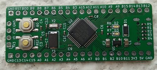
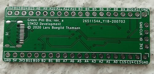
Rev a was ordered in July 2020 and the result showed up like this:
|
|
Notice that the PCB manufacturer missed the holes necessary for the USB-C connector. They acknowledged this to be their mistake and offered to run a second batch at no cost. Due to ONE change in the silk screen (top side have two A9's on the header) this became rev. b.
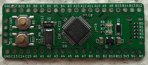
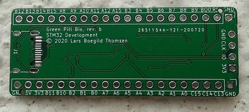
Rev. b
|
|
This time much much better.
With mounted headers and USB-C connector it looks like this:
A few comments on the design. The reason for putting the USB-C connector on the flip side of the board was two fold. First of all, the assembler (JLCPCB) only accept 1 sided mounting, and since I had to hand solder the USB connector it might as well go on the back side. Second it saves space since the resistors necessary can be in the same space. Nevertheless I really didn't like this approach, so it was changed on rev. c.
Rev. c
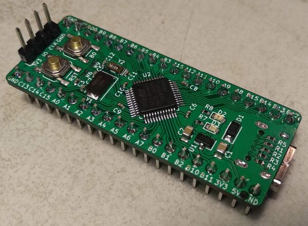
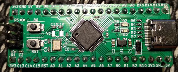
For rev. c a number of changes where made:
- SWO has been added to the programming header which is a 2x3 rather than a 1x4 like it was on earlier revisions.
- Headers have been changed to match the Black Pill boards.
- Since the USB connector is now a JLCPCB part, it has been moved to the top side so that it can be included in assembly.
- Buttons changed to a smaller version (now available as a JLCPCB part).
- Crystal changed from the rather large 8 MHz one to a much smaller (and cheaper) 16 MHz one
GD32 Variant
Because of the global shortage of STM32 MCUs I made a GD32F103 version of this board.
GD32V Variant
GigaDevice also makes a microcontroller series known as GD32VF. Like the GD32E103 these are pin and memory map compatible with the STM32 MCUs, but they are based on a RISC-V rather than an ARM core.
Unfortunately these RISC-V based variants appears to be hard to get. I have contacted GigaDevice through email but they were unable to supply any samples whatsoever and only suggested that I bought from the ONE distributor who have a few in stock (in Poland). I am not sure what is going on but I can only assume that they can not really deliver these processors at all.
I did managed to find an alternative board with this processor - see here: Sipeed Longan Nano

