STM32 Scan I²C bus
Scanning an I2C bus using HAL is really simple.
Videos
The Black Pill board is used in several (not all) of our tutorial videos.
You can watch the video on youtube here: https://www.youtube.com/watch?v=n7vlq_67FI0 (full series here).
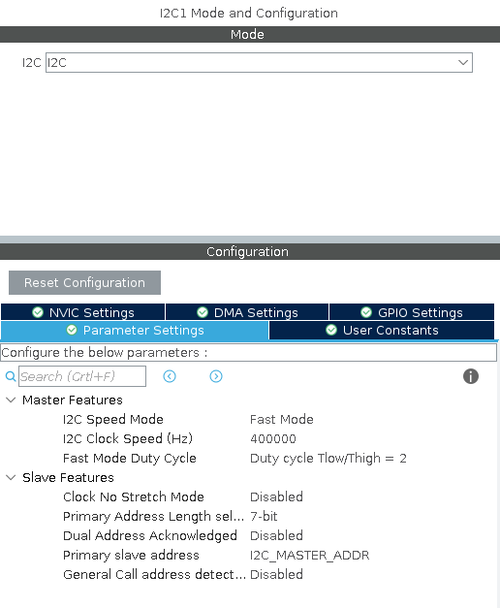
STM32CubeMX Configuration
First configure I²C in STM32CubeMX:
The Code
Once the I²C has been configured, scanning the bus for slaves become a simple matter:
// Go through all possible i2c addresses
  for (uint8_t i = 0; i < 128; i++) {

	  if (HAL_I2C_IsDeviceReady(&hi2c1, (uint16_t)(i<<1), 3, 5) == HAL_OK) {
		  // We got an ack
		  printf("%2x ", i);
	  } else {
		  printf("-- ");
	  }

	  if (i > 0 && (i + 1) % 16 == 0) printf("\n");

  }

  printf("\n");
The HAL_I2C_IsDeviceReady will return HAL_OK if it receives an ACK or an error if not.
With a DFRobot 10 DOF hooked up to the I²C bus, the output from above could be:
-- -- -- -- -- -- -- -- -- -- -- -- -- -- -- --
-- -- -- -- -- -- -- -- -- -- -- -- -- -- 1e --
-- -- -- -- -- -- -- -- -- -- -- -- -- -- -- --
-- -- -- -- -- -- -- -- -- -- -- -- -- -- -- --
-- -- -- -- -- -- -- -- -- -- -- -- -- -- -- --
-- -- -- 53 -- -- -- -- -- -- -- -- -- -- -- --
-- -- -- -- -- -- -- -- 68 -- -- -- -- -- -- --
-- -- -- -- -- -- -- 77 -- -- -- -- -- -- -- --
Notice that I²C addresses are a bit peculiar.
The address itself is shifted 1 bit left and the last (LSB) bit indicates read or write.
If, for example, we look at the ITG-3200, the datasheet states the following:
Binary 01101000 = 0x68, so the 68 in the above output is this particular sensor. However, the HAL_I2C functions will expect the address shifted left:
0x68<<1


