STM32 Beginner - Getting started
How to learn STM32? Getting started with STM32 development is a daunting task. The purpose of this page is to provide some basic pointers on how to make this journey easier.
NOTICE! We have started a new series of tutorial videos on Youtube. Please check STM32 Getting Started Tutorial Video Series (by STM32World).
Even people experienced with Arduino will find the STM32 confusing. Part of that confusion is due to the complexity of the STM32 devices being a lot more complex by themselves:
| Arduino Uno | STM32 "Blue Pill"[1] | STM32 "Black Pill"[2] | |
|---|---|---|---|
| MCU | ATmega328P | STM32F103 | STM32F411 |
| Core | 8-bit | 32-bit ARM Cortex-M3 | 32-bit ARM Cortex-M4 |
| Clock | 16 MHz | 72 MHz | 100 MHz |
| RAM | 2 kB | 32 kB | 128 kB |
| Flash | 32 kB | 64 kB/128 kB | 512 kB |
| USB | Yes[3] | Gadget/Device | Gadget/Device or Host[4] |
| Timers | 2 | 7 | 11 |
| ADCs | 1 (8 channels) | 2 (16 channels) | 1 (16 channels) |
| DMA | No | Yes | Yes |
As can be seen from the basic technical specs, STM32 are much more complex than the simple AtMega328 used on the Arduino boards and because of that complexity (and flexibility) they represent a much steeper learning curve.
Basics
Youtube Videos
We have started a Youtube series. Videos are listed here: STM32 Tutorial Videos.
The first video in the series:
Understanding the part numbers
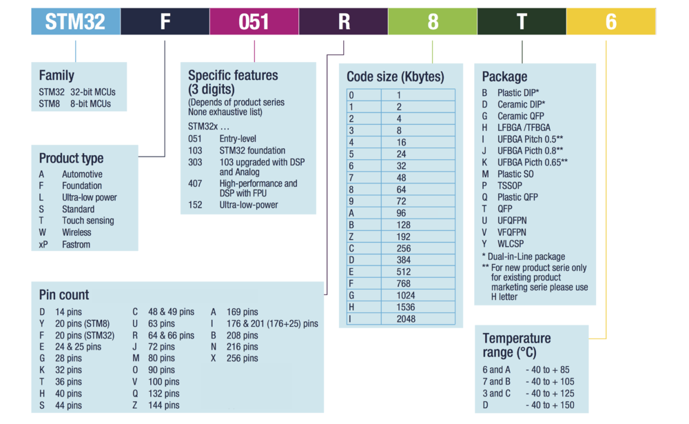
When initially looking into STM32 the sheer number of different "versions" appear baffling. I have no idea how many different STM32 MCUs there are but it has got to be in the "hundreds". Fortunately, ST didn't just pick part numbers at random, there is in fact a system to the madness. ST themselves, on their website, provide the following example:
While not specifically mentioned in the above breakdown, the first number in the features field typically indicate the ARM core version. "STM32F1xx" will be based on an ARM Cortex-M3 core, while "STM32F4xx" are based on a M4 core. Also, different models have different built-in features - number of UARTS, number of I2C ports, number of SPI ports and number of timers. Once you have a development board it is absolutely essential that you local the exact datasheet for the relevant MCU and familiarize yourself with the features (for example, the datasheet for the STM32F411 MCU on the Black Pill is here.) The importance of familiarizing yourself with the relevant datasheet can not be stressed enough.
GPIO Voltage
While most Arduinos run on 5 V, the STM32 can only accept up to 3.3 V (a 5 V supply will fry them). However, while the MCU itself require a <= 3.3 V supply voltage, most GPIO pins are so-called "five volt tolerant"[5], so you can often getting away with interfacing 5V sensors without too much hassle (especially if using open drain and a pull-up as is often the case with I²C).
Clock
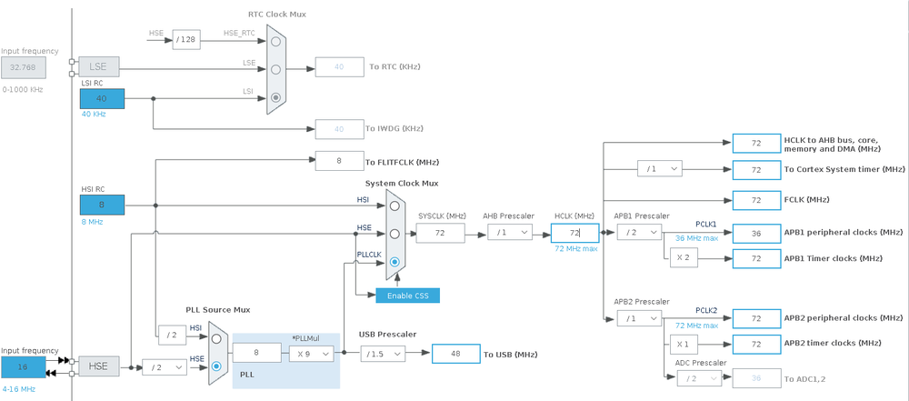
Many MCU run at whatever frequency crystal is attached to it. STM32s are slightly different in this aspect. Most STM32 MCUs can use pretty much any crystal oscillator between 8 GHz and 25 GHz. The crystal oscillator is used internally to drive a PLL (Phase-Locked Loop) which is then used to generate various internal clock signals. This clock configuration is rather complex and it is greatly helped by a graphical editor in STM32CubeMX. Here is an example using a STM32F103 with an external 16 MHz crystal:
Starting from the left, we first see that a 16 MHz external (HSE = High Speed External) crystal oscillator is used (as opposed to the less precise internal 8 MHz HSI (High Speed Internal) RC oscillator. This frequency is divided by two, feeding an 8 MHz clock into the PLL. The PLL will multiply this frequency by 9 to end up with a 72 MHz frequency. In this example USB is enabled and that require a stable and precise 48 MHz clock. This is derived from the 72 MHz by dividing with 1.5. 72 MHz is the highest this MCU will run at so no further prescaling is necessary. The 72 MHz clock is also fed to the DMA busses and the timers.
Bootloader
All STM32 MCUs include a built-in bootloader for "flashing". During startup, the status of the Boot0 pin will be asserted. If "low" (GND) the MCU will start normally. If "high" (= supply voltage - typically 3.3V) the internal bootloader will be executed. This essentially mean that it is very hard to "brick" a STM32 MCU to a point where it can not be recovered.
Prerequisites
ST-Link
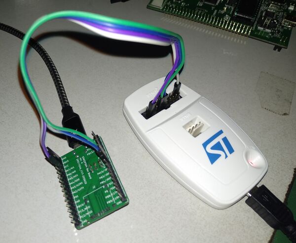
The ST-Link is a device especially designed to flash and debug STM32 MCU's.
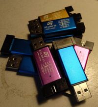
ST can provide these at a reasonable price (< $20) but there are also a lot of Chinese "clones" available. The image to the right show a bunch of these clones.
While the original ST-Link devices provide additional features, the Chinese clones do get the job done and they have one benefit over the original that the pins on the device are clearly labelled. For some incomprehensible reason, ST decided not to label the pins on their device and that is really annoying in daily use.
Development Board
Before diving into the following sections, please note that the first ones are mostly listed here for completion. If you are a beginner in STM32 it is highly recommended that you pick one of the Official ST Development Boards. This can not be stressed enough.
Blue Pill
As mentioned earlier, there's a lot of different STM32 MCU variants and there's almost as many different development boards.
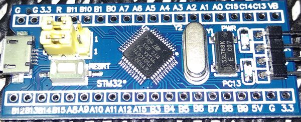
A very popular model was/is the so-called "Blue Pill" board:
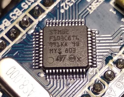
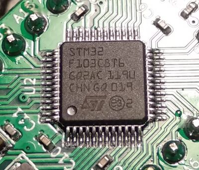
There are different variants of these boards, but they are supposed to include a STM32F103 MCU. The problem is that almost none of them are. There are at least 6-8 Chinese companies making "clones" of the STM32F103 processor. Some of these are probably genuine MCUs with a properly licensed ARM core, that just happens to use the same memory map like the original. Some of these are labelled correctly and identifies themselves as "GD32F103" (from GigaDevice), HK32F103 or something else. Unfortunately some are labelled STM32F103xxx and it can be extremely hard to know which is which:
|
|
| Fake STM32F103 (possibly a HK32) from some random Blue Pill board | Real STM32F103 from my own Green Pill board |
In short, while these boards are extremely cheap and readily available, I would suggest avoiding them completely. Working around the various bugs and lack of knowledge about the MCU just make them a gigantic waste of time.
Black Pill
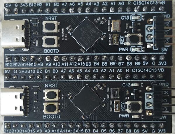
A much better choice are the so-called "Black Pill" boards.
Not only are they generally based on a much more powerful MCU but they are also normally real STM32s[6].
Unlike the Blue Pill boards, the built-in bootloader (activated by pressing the "Boot 0" button during reset) support DFU (flashing over USB). For development however, this is a bit tedious as it require a manual reset before flashing. They are much easier to use if you use a ST-Link device for flashing.
Official ST Development Boards
ST Nucleo
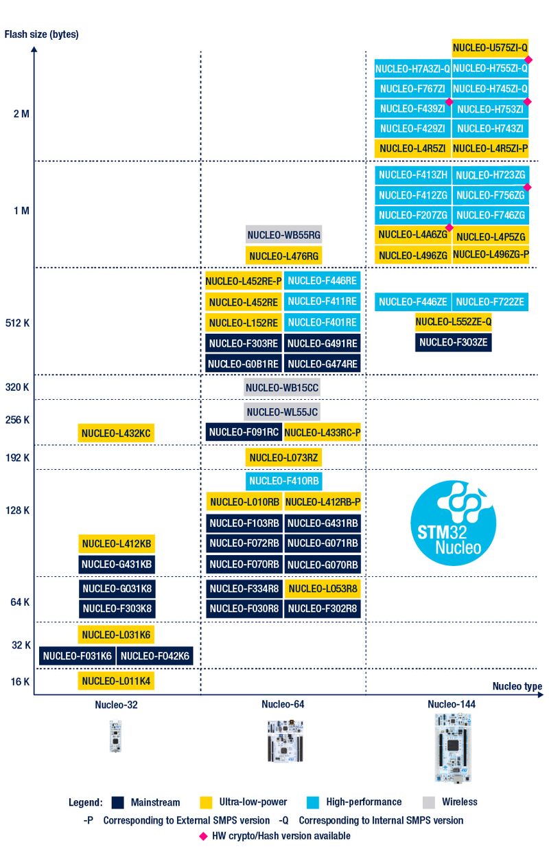
As a beginner the best option by far is one of ST's own Nucleo development boards:
They are available with a wide range of STM32 MCUs, and they are very reasonably priced. If buying a Nucleo board from a reputed supplier (RS or Farnell/Element 14) you can be absolutely certain you got an original MCU.
Best of all, these development boards contain not only the MCU but also a separate ST-Link device! This just makes development and learning a lot easier!
Notice: Most (if not all) if the Nucleo boards do not include a USB connector for the target MCU itself. The USB port on the board is used for flashing alone. If you want to target USB development, look at the Discovery boards instead.
ST Discovery
Like the Nucleo development boards, the Discovery boards are self-contained development boards, including a ST-Link device, making flashing and debugging real easy. They are typically slightly more expensive than the Nucleo boards, but they typically include more hardware, buttons, leds, USB port, display etc.
Arduino
Before diving into using the Arduino IDE with STM32 development boards, I would like to stress that I think it is a horrible approach to learning. The Arduino ecosystem was made to be really simple, quick and easy to get up and running, but as a result of that simplicity they require an Arduino specific bootloader on the target device and they lack "normal" debugging features. When looking for Arduino examples, debugging is generally done by printing statements on a serial console and this is a horribly inefficient way of debugging code.
I suggest you skip this section completely and move on STM32CubeIde.
https://github.com/stm32duino/BoardManagerFiles/raw/main/package_stmicroelectronics_index.json
Stm32CubeIde
Download STM32CubeIDE from here.
Visual Studio Code
To be added (but for now, see STM32 development and debugging using VSCode for details.)
Miscellaneous Links
Arduino
To be added
Stm32CubeIde
- STM32CubeIde Download (registration required)
References
- ↑ https://www.st.com/resource/en/datasheet/stm32f103c8.pdf
- ↑ https://www.st.com/resource/en/datasheet/stm32f411ce.pdf
- ↑ Flashing/Serial debug only
- ↑ The STM32F411 can run both Gadget and Host, but the actual development board might not support Host mode.
- ↑ There are some exceptions. When configured as an analog input pin, the pins are not 5V tolerant!
- ↑ I simply don't think fake [[STM32F411 exists at the moment even though that will probably change at some point
