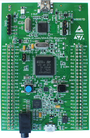
STM32F407G-DISC1
Rant Video
This board qualified for a rant video of useless idiotic development boards.
Brain dead design
The ST Discovery boards are truly brain dead in their design (hey ST, send me an email and ask nicely and I can help you out - for a fee of course).
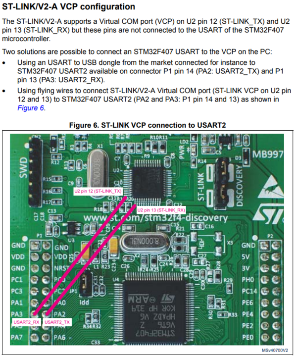
For example, the Discovery boards, like the Nucleo boards, contain a built-in ST-Link device. On the STM32F407G-DISC1 that ST-Link is a V/2-1 device which also includes a virtual serial port over the same USB. Unfortunately, the Datasheet includes the following gem:
So, to use the serial port in the ST-Link the user will have to solder two thin wires from directly on the MCU to a couple of header pins. They didn't even bother with a solder pad or test point.
What on earth possessed them? When designing the Green Pill there was very limited space to use, but it is not as if they are short on space on this board. There can only be one of two reasons for this. Either whoever designed it was incredible stupid and/or extremely lazy.
Fixing brain dead design
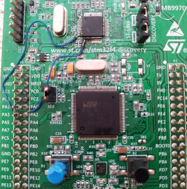
The above bit of idiocy can be fixed as described. Here's how it can look:
Notice I managed to melt a bit of the user button trying to get the soldering iron into the back of the header. I also had to go back and clean up the solder a bit - I think I managed to create a short. But a lot of flux managed to clean that out.
MEMS motion sensor
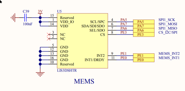
The STM32F407G-DISC1 contains a MEMS motion sensor, the LIS3DSH.
The MEMS sensor is wired up to a SPI peripheral like this:
Audio
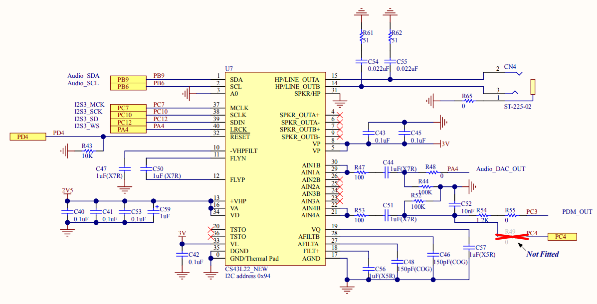
The STM32F407G-DISC1 board contains a CS43L22 I2S audio out and amplifier chip wired up like this:
Notice that there is a slight mistake when ST claims the I²C address to be 0x94. I²C addresses are 7-bit, so there is no way it can be that. However, when used, I²C addresses are shifted left by 1 bit and the remaining bit indicates read or write. Therefor, the actual I²C address is 0x4A. Shifted left 1 bit is giving us 0x94 as the write address and 0x95 as the read address.
