STM32 LED Blink
When learning a new programming language, programmers often - if not always - begin with a humble "hello world" application, which will print "Hello World!" on the display. As common as that, when it comes to embedded programming (where a display might not be available) a typical "first application" is one which will blink a led. And for this reason, most development boards comes with one or more leds which can be controlled with a GPIO pin.
In this article, I will be using my own Green Pill development board, which for all intents and purposes is comparable to the common Blue Pill. The board is based on an STM32F103 processor, includes a 8 MHz external crystal and has got a led attached to the PC13 GPIO pin.
Common Settings
For these examples, I will be using ST's Stm32CubeIde, which includes Stm32CubeMx. Stm32CubeMx is used to "configure" the processor.
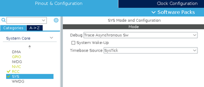
When starting a new project in Stm32CubeIde, I generally go through some common settings. First step I configure the Serial Wire debug (including the trace):
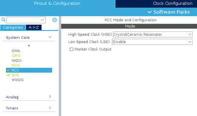
Second step is to configure the CPU to enable the external crystal:
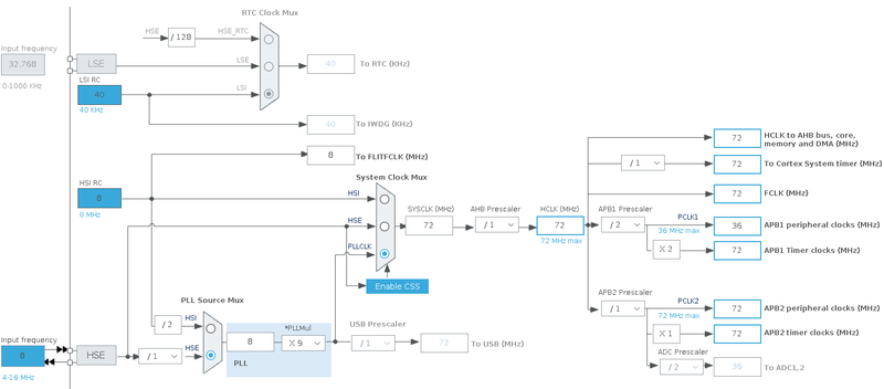
Final step is to configure the various clocks:
The important values here is the value of the external crystal (in this case 8 MHz), the value of HCLK, which is the frequency the processor will run at. Also important to notice is the value of the APB1 Timer Clocks. This is the frequency at which the timers will operate (in this case 72 MHz - remember this value for later examples).
Main Loop With Delay
This approach - while wildly misguided - is often seen in examples, particularly Arduino based ones. In this approach, the led is simply toggled in the main loop of the program, with an appropriate delay. Using Stm32CubeIde and it's HAL libraries, the main loop will look something like:
  /* Infinite loop */
  /* USER CODE BEGIN WHILE */
  while (1)
  {

	// Toggle the LED
	HAL_GPIO_TogglePin(GPIOC, GPIO_PIN_13);

	// Wait for 100 ms
	HAL_Delay(100);

	// Rinse and repeat :)

    /* USER CODE END WHILE */

    /* USER CODE BEGIN 3 */
  }
  /* USER CODE END 3 */
The approach is simple and easily understood. It will toggle the led, not caring what the previous state was, and then wait for 100 ms. The result will be approximately 5 "blinks" per second:


