Difference between revisions of "STM32 WS2812B"
| Line 13: | Line 13: | ||
[[File:WS2812B Chain.png|800px]] | [[File:WS2812B Chain.png|800px]] | ||
| − | When sending data each LED need 24 bit - 8 bit for each color. The first LED in the chain will "use" the first 24 bit and then pass any following bit to the next LED in the chain and so forth | + | When sending data each LED need 24 bit - 8 bit for each color. The first LED in the chain will "use" the first 24 bit and then pass any following bit to the next LED in the chain and so forth. After a reset (a pause with no data) this cycle repeats. |
[[File:WS2812B Data Transmission Method.png|600px]] | [[File:WS2812B Data Transmission Method.png|600px]] | ||
| + | |||
| + | For each individual LED the 24 bits are expected like this: | ||
| + | |||
| + | [[File:WS2812 bits.png|800px]] | ||
| + | |||
| + | Notice that for the WS2812B the order is GRB (Green, Red, Blue). | ||
Revision as of 02:35, 22 April 2021
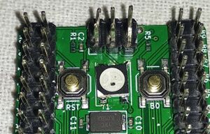
When developing the STM32Dev board a WS2812B RGB LED was including connected to the PC6 GPIO.
The WS2812B LED contains 3 LEDS: red, green and blue and each of these LEDS can be set at 256 different brightness levels. These levels are controlled with a bit stream running at 800 kHz and multiple LEDS (up to 1000-ish) can be chained after each other.
Searching the Internet there are a lot of suggestions and implementations dealing with the ws2812 LEDs, so obviously I decided to take a different approach. This approach is described on this page.
Protocol Analysis
WS2812 LEDs are daisy chained together like this:
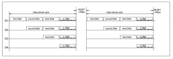
When sending data each LED need 24 bit - 8 bit for each color. The first LED in the chain will "use" the first 24 bit and then pass any following bit to the next LED in the chain and so forth. After a reset (a pause with no data) this cycle repeats.
For each individual LED the 24 bits are expected like this:
Notice that for the WS2812B the order is GRB (Green, Red, Blue).
Library on Github
The library is available on Github:
https://github.com/lbthomsen/stm32-ws2812b


