Difference between revisions of "STM32 Scan I²C bus"
Jump to navigation
Jump to search
| (6 intermediate revisions by the same user not shown) | |||
| Line 1: | Line 1: | ||
[[Category:STM32]][[Category:STM32 Development]][[Category:STM32CubeMX]][[Category:STM32CubeIde]][[Category:STM32 HAL]][[Category:I²C]]{{metadesc|How to scan an I2C bus using STM32 HAL}} | [[Category:STM32]][[Category:STM32 Development]][[Category:STM32CubeMX]][[Category:STM32CubeIde]][[Category:STM32 HAL]][[Category:I²C]]{{metadesc|How to scan an I2C bus using STM32 HAL}} | ||
| − | Scanning an [[I2C]] bus using HAL is really simple. First configure [[I²C]] in [[STM32CubeMX]]: | + | Scanning an [[I2C]] bus using [[STM32 HAL|HAL]] is really simple. First configure [[I²C]] in [[STM32CubeMX]]: |
| − | [[File:I2c Config.png| | + | [[File:I2c Config.png|500px]] |
Once the [[I²C]] has been configured, scanning the bus for slaves become a simple matter: | Once the [[I²C]] has been configured, scanning the bus for slaves become a simple matter: | ||
| Line 27: | Line 27: | ||
The HAL_I2C_IsDeviceReady will return HAL_OK if it receives an ACK or an error if not. | The HAL_I2C_IsDeviceReady will return HAL_OK if it receives an ACK or an error if not. | ||
| − | + | With a [[STM32 DFRobot 10 DOF|DFRobot 10 DOF]] hooked up to the I²C bus, the output from above could be: | |
<pre> | <pre> | ||
| Line 44: | Line 44: | ||
[[File:I²C 7-bit Addresses.png|600px]] | [[File:I²C 7-bit Addresses.png|600px]] | ||
| − | The address itself is shifted 1 bit left and the last (LSB) bit indicates read or write. | + | The address itself is shifted 1 bit left and the last (LSB) bit indicates read or write. |
| − | + | If, for example, we look at the [https://ipfs.io/ipfs/QmUi4EmwjuxEdNTCRG8PEG6dEgpzSjtjQwwCFEy5VD1Kgr/2645523.pdf ITG-3200], the datasheet states the following: | |
| − | + | [[File:ITG-3200 I2C address.png|800px]] | |
| − | + | Binary 01101000 = 0x68, so the 68 in the above output is this particular sensor. However, the HAL_I2C functions will expect the address shifted left: | |
| + | |||
| + | 0x68<<1 | ||
Latest revision as of 11:40, 13 July 2021
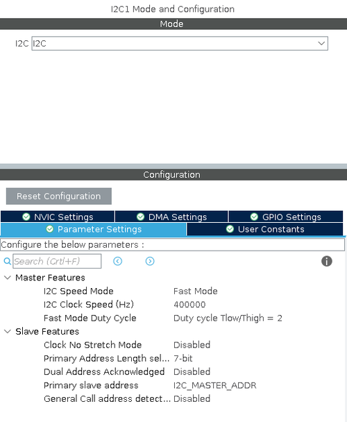
Scanning an I2C bus using HAL is really simple. First configure I²C in STM32CubeMX:
Once the I²C has been configured, scanning the bus for slaves become a simple matter:
// Go through all possible i2c addresses
  for (uint8_t i = 0; i < 128; i++) {

	  if (HAL_I2C_IsDeviceReady(&hi2c1, (uint16_t)(i<<1), 3, 5) == HAL_OK) {
		  // We got an ack
		  printf("%2x ", i);
	  } else {
		  printf("-- ");
	  }

	  if (i > 0 && (i + 1) % 16 == 0) printf("\n");

  }

  printf("\n");
The HAL_I2C_IsDeviceReady will return HAL_OK if it receives an ACK or an error if not.
With a DFRobot 10 DOF hooked up to the I²C bus, the output from above could be:
-- -- -- -- -- -- -- -- -- -- -- -- -- -- -- --
-- -- -- -- -- -- -- -- -- -- -- -- -- -- 1e --
-- -- -- -- -- -- -- -- -- -- -- -- -- -- -- --
-- -- -- -- -- -- -- -- -- -- -- -- -- -- -- --
-- -- -- -- -- -- -- -- -- -- -- -- -- -- -- --
-- -- -- 53 -- -- -- -- -- -- -- -- -- -- -- --
-- -- -- -- -- -- -- -- 68 -- -- -- -- -- -- --
-- -- -- -- -- -- -- 77 -- -- -- -- -- -- -- --
Notice that I²C addresses are a bit peculiar.
The address itself is shifted 1 bit left and the last (LSB) bit indicates read or write.
If, for example, we look at the ITG-3200, the datasheet states the following:
Binary 01101000 = 0x68, so the 68 in the above output is this particular sensor. However, the HAL_I2C functions will expect the address shifted left:
0x68<<1


