Difference between revisions of "STM32 LED Blink"
| (36 intermediate revisions by the same user not shown) | |||
| Line 1: | Line 1: | ||
| − | [[Category:C]] [[Category:STM32 Development]] [[Category:STM32CubeMX]] [[Category:STM32CubeIde]] [[Category:Embedded]] [[Category:STM32]] {{metadesc| | + | [[Category:C]] [[Category:STM32 Development]] [[Category:STM32 HAL]] [[Category:STM32 LL]] [[Category:STM32CubeMX]] [[Category:STM32CubeIde]] [[Category:Embedded]] [[Category:STM32]] {{metadesc|6 different ways to flash a LED using STM32 HAL and/or LL}} |
| − | When learning a new programming language, programmers often | + | When learning a new programming language, programmers often, if not always, begin with a humble "hello world" application, which will print "Hello World!" on the display. As common as that, when it comes to embedded programming (where a display might not be available), a typical "first application" is one which will blink a [[led]]. And for this reason, most development boards comes with one or more [[led]]s which can be controlled with a [[GPIO]] pin. |
| − | In this article, I will be using my own [[Green Pill]] development board, which for all intents and purposes is comparable to the common [[Blue Pill]]. The board is based on an STM32F103 processor, includes a 8 MHz external crystal and has got a [[led]] attached to the PC13 [[GPIO]] pin. | + | In this article, [[User:Lth|I]] will be using my own [[Green Pill]] development board, which for all intents and purposes is comparable to the common [[Blue Pill]]. The board is based on an STM32F103 processor, includes a 8 MHz external crystal and has got a [[led]] attached to the PC13 [[GPIO]] pin. |
| − | == Common Settings == | + | == New Youtube Video == |
| + | |||
| + | I started a Youtube video series and one of the first videos show how to start a project and implement a blink app: | ||
| + | |||
| + | === Wrong Approach === | ||
| + | |||
| + | {{#ev:youtube|g-RVJDnlHd0}} | ||
| + | |||
| + | === Right Approach === | ||
| + | |||
| + | {{#ev:youtube|rQDa_vxYM2Q}} | ||
| + | |||
| + | == HAL == | ||
| + | |||
| + | Using the [[STM32]] [[HAL]] from [[ST]] there are a number of different ways to blink a LED. These are discussed in the following sections. | ||
| + | |||
| + | === Common Settings === | ||
For these examples, I will be using [[ST]]'s [https://www.st.com/en/development-tools/stm32cubeide.html Stm32CubeIde], which includes [https://www.st.com/en/development-tools/stm32cubeide.html Stm32CubeMx]. Stm32CubeMx is used to "configure" the processor. | For these examples, I will be using [[ST]]'s [https://www.st.com/en/development-tools/stm32cubeide.html Stm32CubeIde], which includes [https://www.st.com/en/development-tools/stm32cubeide.html Stm32CubeMx]. Stm32CubeMx is used to "configure" the processor. | ||
| Line 22: | Line 38: | ||
The important values here is the value of the external crystal (in this case 8 MHz), the value of HCLK, which is the frequency the processor will run at. Also important to notice is the value of the APB1 Timer Clocks. This is the frequency at which the timers will operate (in this case 72 MHz - remember this value for later examples). | The important values here is the value of the external crystal (in this case 8 MHz), the value of HCLK, which is the frequency the processor will run at. Also important to notice is the value of the APB1 Timer Clocks. This is the frequency at which the timers will operate (in this case 72 MHz - remember this value for later examples). | ||
| − | == Main Loop With Delay == | + | === Main Loop With Delay === |
| − | This approach | + | This approach, while quite misguided, is often seen in examples, particularly Arduino based ones. In this approach, the [[led]] is simply toggled in the main loop of the program, with an appropriate delay. Using Stm32CubeIde and it's HAL libraries, the main loop will look something like: |
<pre> | <pre> | ||
| Line 49: | Line 65: | ||
The approach is simple and easily understood. It will toggle the [[led]], not caring what the previous state was, and then wait for 500 ms. The result will be approximately 1 blinks per second: | The approach is simple and easily understood. It will toggle the [[led]], not caring what the previous state was, and then wait for 500 ms. The result will be approximately 1 blinks per second: | ||
| − | {{#ev:youtube| | + | {{#ev:youtube|nH4LHFqUg2U}} |
The keyword in the above description is "approximately". I made the claim earlier that this approach was generally misguided and that is part of the problem. In reality, this approach has at least two problems. | The keyword in the above description is "approximately". I made the claim earlier that this approach was generally misguided and that is part of the problem. In reality, this approach has at least two problems. | ||
| Line 57: | Line 73: | ||
The second problem is the "HAL_Delay". While that is running, the processor is tied up in doing "nothing". While doing nothing but flashing a [[led]] that is of course OK, but typically one would want the processor to do "other things" and if that is the case the actual LED frequency will be even more unpredictable. | The second problem is the "HAL_Delay". While that is running, the processor is tied up in doing "nothing". While doing nothing but flashing a [[led]] that is of course OK, but typically one would want the processor to do "other things" and if that is the case the actual LED frequency will be even more unpredictable. | ||
| − | == Main Loop Without Delay == | + | You can find this example here: [https://github.com/lbthomsen/greenpill/tree/master/blink1 https://github.com/lbthomsen/greenpill/tree/master/blink1]. |
| + | |||
| + | === Main Loop Without Delay === | ||
A somewhat better approach would be to check the time in the main loop - something like this: | A somewhat better approach would be to check the time in the main loop - something like this: | ||
| Line 65: | Line 83: | ||
/* USER CODE BEGIN WHILE */ | /* USER CODE BEGIN WHILE */ | ||
| − | uint32_t then = 0; | + | uint32_t then = 0, now = 0; |
while (1) | while (1) | ||
| Line 71: | Line 89: | ||
// Check the current tick | // Check the current tick | ||
| − | + | now = HAL_GetTick(); | |
| − | if (now | + | if (now - then >= 500) { // Only if the current tick is 500 ms after the last |
HAL_GPIO_TogglePin(GPIOC, GPIO_PIN_13); // Toggle LED | HAL_GPIO_TogglePin(GPIOC, GPIO_PIN_13); // Toggle LED | ||
| Line 90: | Line 108: | ||
</pre> | </pre> | ||
| − | Compared to the previous example, this one is still running in the main loop, but without a forced delay. Instead of the delay, this version will check the "HAL_GetTick()". | + | Compared to the previous example, this one is still running in the main loop, but without a forced delay. Instead of the delay, this version will check the "HAL_GetTick()". If no long tasks are being run which may block the main loop and the exact timing of the LED is not overly critical, this approach is perfectly acceptable. |
| + | |||
| + | When starting a new project I quite often include above snippet. It gives me an instant visual check if my code is still running. Any code which causes a fault will halt the blinking. | ||
| + | |||
| + | You can find this example here: [https://github.com/lbthomsen/greenpill/tree/master/blink2 https://github.com/lbthomsen/greenpill/tree/master/blink2] | ||
| − | == Using a timer == | + | === Using a timer === |
While the previous example is much better than the first, there's still room for improvement and that improvement will come from using one of the STM32F103 timers. | While the previous example is much better than the first, there's still room for improvement and that improvement will come from using one of the STM32F103 timers. | ||
| Line 98: | Line 120: | ||
A third approach to blinking a [[led]] is to use one of the built-in timers of the CPU. | A third approach to blinking a [[led]] is to use one of the built-in timers of the CPU. | ||
| − | First step is to use [[ | + | First step is to use [[STM32CubeMX]] to configure the timer. Begin by enabling a clock source: |
[[File:Blink Tim4 - source.png|600px]] | [[File:Blink Tim4 - source.png|600px]] | ||
| Line 169: | Line 191: | ||
</pre> | </pre> | ||
| − | That is it - notice that the while loop is completely empty. | + | That is it - notice that the while loop is completely empty. Contrary to the two previous examples this one will run at a precise frequency controlled by the timer. |
| − | == Pulse Width Modulation (PWM) == | + | You can find this example here: [https://github.com/lbthomsen/greenpill/tree/master/blink3 https://github.com/lbthomsen/greenpill/tree/master/blink3] |
| + | |||
| + | === Pulse Width Modulation (PWM) === | ||
In the previous example, the actual timing of the blink was offloaded to a hardware timer. The actual toggling of the LED was still handled in the main processor by an [[Interrupt Service Routine]] (ISR). The ISR doesn't do much more than toggling a [[GPIO]] so it will be really quick. However, | In the previous example, the actual timing of the blink was offloaded to a hardware timer. The actual toggling of the LED was still handled in the main processor by an [[Interrupt Service Routine]] (ISR). The ISR doesn't do much more than toggling a [[GPIO]] so it will be really quick. However, | ||
| Line 177: | Line 201: | ||
The final approach to blinking a [[LED]] would be to use [[PWM]] ([[Pulse-width modulation]]). Unfortunately, the PC13 [[GPIO]] port used in the previous examples, is not able to do hardware [[PWM]], so in order to demonstrate this approach, the built-in LED must be hooked up to a GPIO which allow PWM (we'll be using PB6 in this example). By default, PC13 will be in "input" mode (high impedance), so it is a simple matter of running a jumper wire from PC13 to PB6: | The final approach to blinking a [[LED]] would be to use [[PWM]] ([[Pulse-width modulation]]). Unfortunately, the PC13 [[GPIO]] port used in the previous examples, is not able to do hardware [[PWM]], so in order to demonstrate this approach, the built-in LED must be hooked up to a GPIO which allow PWM (we'll be using PB6 in this example). By default, PC13 will be in "input" mode (high impedance), so it is a simple matter of running a jumper wire from PC13 to PB6: | ||
| − | [[File:PC13 to PB6 jumper.jpg| | + | [[File:PC13 to PB6 jumper.jpg|600px]] |
| − | The next step will be to use | + | The next step will be to use [[STM32CubeMX]] to reconfigure the timer and GPIO pins. |
| − | [[File:Tim4 configured for PWM on Channel 1.png| | + | [[File:Tim4 configured for PWM on Channel 1.png|600px]] |
Also remember to reset the PC13 as we want to keep that in high impedance input mode. | Also remember to reset the PC13 as we want to keep that in high impedance input mode. | ||
| − | [[File:Tim4 PWM Pinout.png| | + | [[File:Tim4 PWM Pinout.png|600px]] |
Finally, we need to add an extra "constant" for the PWM duty cycle: | Finally, we need to add an extra "constant" for the PWM duty cycle: | ||
| − | [[File:Tim4 PWM User Constants.png| | + | [[File:Tim4 PWM User Constants.png|600px]] |
and use that constant as the actual duty cycle: | and use that constant as the actual duty cycle: | ||
| − | [[File:Tim4 PWM Duty Cycle.png| | + | [[File:Tim4 PWM Duty Cycle.png|600px]] |
We are now done with the configuration in Stm32CubeMX and we can generate the code. | We are now done with the configuration in Stm32CubeMX and we can generate the code. | ||
| Line 219: | Line 243: | ||
And that is about it - not a single CPU cycle is "wasted" on flashing the LED. It runs entirely in the peripheral hardware. | And that is about it - not a single CPU cycle is "wasted" on flashing the LED. It runs entirely in the peripheral hardware. | ||
| + | |||
| + | You can find this example here: [https://github.com/lbthomsen/greenpill/tree/master/blink4 https://github.com/lbthomsen/greenpill/tree/master/blink4] | ||
| + | |||
| + | == LL (Low Level) == | ||
| + | |||
| + | The examples in the previous section all used [[ST]]'s [[HAL]] (Hardware Abstraction) Library. These libraries are quite complex and they do take a lot of memory. The [[HAL]] library is build on top of some more hardware specific low level libraries known as [[LL]]. Fortunately, even with [[STM32CubeMX]], it is possible to avoid the [[HAL]] library and stick exclusively with the low level. | ||
| + | |||
| + | === Common Settings === | ||
| + | |||
| + | Like the earlier HAL examples, the starting point of the LL examples is [[STM32CubeMX]]. This time however, we switch the library from HAL to LL: | ||
| + | |||
| + | [[File:Settings for LL.png|1000px]] | ||
| + | |||
| + | === Main Loop Without Delay === | ||
| + | |||
| + | In principle this works almost exactly like the [[#Main Loop Without Delay|HAL example]]. The main difference is that we need to do a bit of housekeeping to maintain the counter. | ||
| + | |||
| + | First step is to enable the systick interrupt. | ||
| + | |||
| + | <pre> | ||
| + | /* USER CODE BEGIN 2 */ | ||
| + | |||
| + | // By default LL SysTick interrupt is not enabled - let's enable it | ||
| + | LL_SYSTICK_EnableIT(); | ||
| + | |||
| + | /* USER CODE END 2 */ | ||
| + | </pre> | ||
| + | |||
| + | The interrupt handler is already defined in `stm32f4xx_it.c`. We just add a counter: | ||
| + | |||
| + | <pre> | ||
| + | /* USER CODE BEGIN PV */ | ||
| + | |||
| + | // Incremented by 1 ms systick interrupt | ||
| + | uint32_t systick_counter = 0; | ||
| + | |||
| + | /* USER CODE END PV */ | ||
| + | |||
| + | ...... | ||
| + | |||
| + | void SysTick_Handler(void) | ||
| + | { | ||
| + | /* USER CODE BEGIN SysTick_IRQn 0 */ | ||
| + | |||
| + | // Just increase the systick variable | ||
| + | systick_counter++; | ||
| + | |||
| + | /* USER CODE END SysTick_IRQn 0 */ | ||
| + | |||
| + | /* USER CODE BEGIN SysTick_IRQn 1 */ | ||
| + | |||
| + | /* USER CODE END SysTick_IRQn 1 */ | ||
| + | } | ||
| + | </pre> | ||
| + | |||
| + | Finally we create a helper function to get this variable. In `stm32f4xx_it.h` | ||
| + | |||
| + | <pre> | ||
| + | /* USER CODE BEGIN EFP */ | ||
| + | |||
| + | uint32_t get_systick_counter(); | ||
| + | |||
| + | /* USER CODE END EFP */ | ||
| + | </pre> | ||
| + | |||
| + | And in `stm32f4xx_it.c`: | ||
| + | |||
| + | <pre> | ||
| + | /* USER CODE BEGIN 1 */ | ||
| + | |||
| + | uint32_t get_systick_counter() { | ||
| + | // Return current value of systick_counter variable | ||
| + | return systick_counter; | ||
| + | } | ||
| + | |||
| + | /* USER CODE END 1 */ | ||
| + | </pre> | ||
| + | |||
| + | We now, like when using HAL, got a systick counter which increments every 1ms and our main program loop can be implemented like this: | ||
| + | |||
| + | <pre> | ||
| + | /* USER CODE BEGIN WHILE */ | ||
| + | |||
| + | uint32_t then = 0, now = 0; | ||
| + | |||
| + | for (;;) | ||
| + | { | ||
| + | |||
| + | now = get_systick_counter(); | ||
| + | if (now - then >= 500) { | ||
| + | LL_GPIO_TogglePin(LED_GPIO_Port, LED_Pin); | ||
| + | then = now; | ||
| + | } | ||
| + | |||
| + | /* USER CODE END WHILE */ | ||
| + | |||
| + | /* USER CODE BEGIN 3 */ | ||
| + | } | ||
| + | /* USER CODE END 3 */ | ||
| + | </pre> | ||
| + | |||
| + | You can find this example here: [https://github.com/lbthomsen/blackpill/tree/master/ll_blink1 https://github.com/lbthomsen/blackpill/tree/master/ll_blink1] | ||
| + | |||
| + | === Timer Interrupt === | ||
| + | |||
| + | Like in the previous example [[#Using a timer|Using a timer]], a periodic timer interrupt can be used to toggle the LED on and off. | ||
| + | |||
| + | First, configure the TIM4 exactly like in the previous example, but ensure the advanced config is switched to [[LL]] rather than [[HAL]]. | ||
| + | |||
| + | While [[HAL]] provides a functioning interrupt handler, LL just provide an empty function, so first step is to modify this in `stm32f4xx_it.c`: | ||
| + | |||
| + | <pre> | ||
| + | void TIM4_IRQHandler(void) | ||
| + | { | ||
| + | /* USER CODE BEGIN TIM4_IRQn 0 */ | ||
| + | |||
| + | LL_TIM_ClearFlag_UPDATE(TIM4); | ||
| + | |||
| + | tim4_interrupt_callback(); | ||
| + | |||
| + | /* USER CODE END TIM4_IRQn 0 */ | ||
| + | /* USER CODE BEGIN TIM4_IRQn 1 */ | ||
| + | |||
| + | /* USER CODE END TIM4_IRQn 1 */ | ||
| + | } | ||
| + | </pre> | ||
| + | |||
| + | Essentially we just need to clear the flag so that the [[MCU]] know we have handled the interrupt. | ||
| + | |||
| + | In `main.c` we create our callback function: | ||
| + | |||
| + | <pre> | ||
| + | /* USER CODE BEGIN 0 */ | ||
| + | |||
| + | void tim4_interrupt_callback() { | ||
| + | LL_GPIO_TogglePin(LED_GPIO_Port, LED_Pin); | ||
| + | } | ||
| + | |||
| + | /* USER CODE END 0 */ | ||
| + | </pre> | ||
| + | |||
| + | Now we can start the counter and enable the interrupt: | ||
| + | |||
| + | <pre> | ||
| + | /* USER CODE BEGIN 2 */ | ||
| + | |||
| + | LL_TIM_EnableCounter(TIM4); | ||
| + | LL_TIM_EnableIT_UPDATE(TIM4); | ||
| + | |||
| + | /* USER CODE END 2 */ | ||
| + | </pre> | ||
| + | |||
| + | And that is it - the LED is happily flashing once per second. | ||
| + | |||
| + | You can find this example here: [https://github.com/lbthomsen/blackpill/tree/master/ll_blink2 https://github.com/lbthomsen/blackpill/tree/master/ll_blink2] | ||
Latest revision as of 15:45, 17 September 2024
When learning a new programming language, programmers often, if not always, begin with a humble "hello world" application, which will print "Hello World!" on the display. As common as that, when it comes to embedded programming (where a display might not be available), a typical "first application" is one which will blink a led. And for this reason, most development boards comes with one or more leds which can be controlled with a GPIO pin.
In this article, I will be using my own Green Pill development board, which for all intents and purposes is comparable to the common Blue Pill. The board is based on an STM32F103 processor, includes a 8 MHz external crystal and has got a led attached to the PC13 GPIO pin.
New Youtube Video
I started a Youtube video series and one of the first videos show how to start a project and implement a blink app:
Wrong Approach
Right Approach
HAL
Using the STM32 HAL from ST there are a number of different ways to blink a LED. These are discussed in the following sections.
Common Settings
For these examples, I will be using ST's Stm32CubeIde, which includes Stm32CubeMx. Stm32CubeMx is used to "configure" the processor.
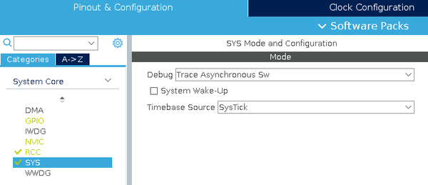
When starting a new project in Stm32CubeIde, I generally go through some common settings. First step I configure the Serial Wire debug (including the trace):
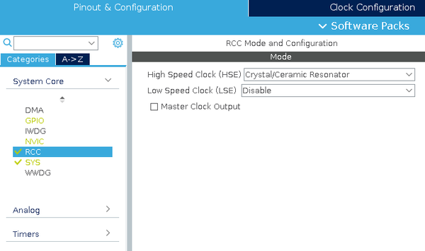
Second step is to configure the CPU to enable the external crystal:
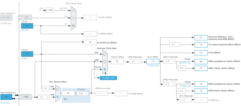
Final step is to configure the various clocks:
The important values here is the value of the external crystal (in this case 8 MHz), the value of HCLK, which is the frequency the processor will run at. Also important to notice is the value of the APB1 Timer Clocks. This is the frequency at which the timers will operate (in this case 72 MHz - remember this value for later examples).
Main Loop With Delay
This approach, while quite misguided, is often seen in examples, particularly Arduino based ones. In this approach, the led is simply toggled in the main loop of the program, with an appropriate delay. Using Stm32CubeIde and it's HAL libraries, the main loop will look something like:
  /* Infinite loop */
  /* USER CODE BEGIN WHILE */
  while (1)
  {

	// Toggle the LED
	HAL_GPIO_TogglePin(GPIOC, GPIO_PIN_13);

	// Wait for 500 ms
	HAL_Delay(500);

	// Rinse and repeat :)

    /* USER CODE END WHILE */

    /* USER CODE BEGIN 3 */
  }
  /* USER CODE END 3 */
The approach is simple and easily understood. It will toggle the led, not caring what the previous state was, and then wait for 500 ms. The result will be approximately 1 blinks per second:
The keyword in the above description is "approximately". I made the claim earlier that this approach was generally misguided and that is part of the problem. In reality, this approach has at least two problems.
First of all, the call of both HAL_GPIO_TogglePin and HAL_Delay are not single instructions, so the actual time spend in the loop will be "a tiny bit" longer than 500 ms resulting in a frequency which is slightly below the intended 1 Hz. Sure, it will only be "off" by a few micro seconds, but it will be off!
The second problem is the "HAL_Delay". While that is running, the processor is tied up in doing "nothing". While doing nothing but flashing a led that is of course OK, but typically one would want the processor to do "other things" and if that is the case the actual LED frequency will be even more unpredictable.
You can find this example here: https://github.com/lbthomsen/greenpill/tree/master/blink1.
Main Loop Without Delay
A somewhat better approach would be to check the time in the main loop - something like this:
  /* Infinite loop */
  /* USER CODE BEGIN WHILE */

  uint32_t then = 0, now = 0;

  while (1)
  {

	// Check the current tick
	now = HAL_GetTick();
	if (now - then >= 500) { // Only if the current tick is 500 ms after the last

		HAL_GPIO_TogglePin(GPIOC, GPIO_PIN_13); // Toggle LED

		then = now; // Reset then = now
	}

	// Other stuff can be done here without affecting the blink frequency as long as
	// whatever is being done take less than 500 ms.

    /* USER CODE END WHILE */

    /* USER CODE BEGIN 3 */
  }
  /* USER CODE END 3 */
}
Compared to the previous example, this one is still running in the main loop, but without a forced delay. Instead of the delay, this version will check the "HAL_GetTick()". If no long tasks are being run which may block the main loop and the exact timing of the LED is not overly critical, this approach is perfectly acceptable.
When starting a new project I quite often include above snippet. It gives me an instant visual check if my code is still running. Any code which causes a fault will halt the blinking.
You can find this example here: https://github.com/lbthomsen/greenpill/tree/master/blink2
Using a timer
While the previous example is much better than the first, there's still room for improvement and that improvement will come from using one of the STM32F103 timers.
A third approach to blinking a led is to use one of the built-in timers of the CPU.
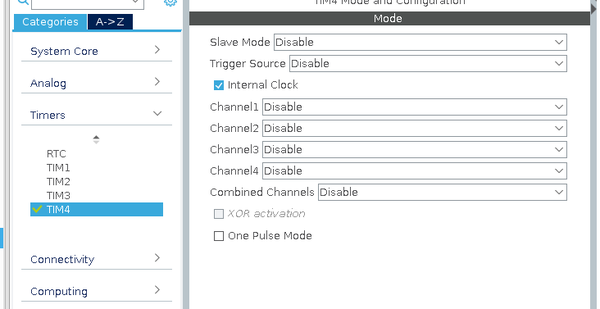
First step is to use STM32CubeMX to configure the timer. Begin by enabling a clock source:
Enabling the Internal Clock means the timer will be run by the ADB1 clock, which was configured earlier to run at 72 MHz.
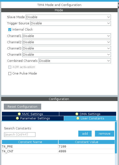
We next need to divide this down to a usable frequency. We define two User Constants 'T4_PRE' and 'T4_CNT':
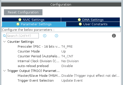
Switch to the Parameter Settings tab and use the above constants in place of Prescaler and Counter:
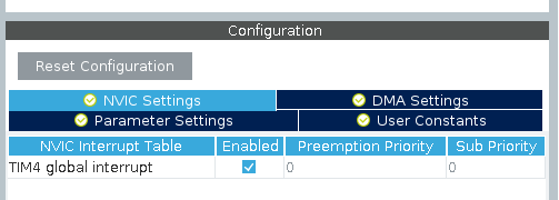
The final step is to enable the Global Interrupt for this timer:
We can now generate code and finish the last few things.
First - while the User Constants are defined in the header file, I like to put them directly in the source like this:
/* Private define ------------------------------------------------------------*/
/* USER CODE BEGIN PD */

#define T4_PRE 7199
#define T4_CNT 4999

/* USER CODE END PD */
We now need to define the Interrupt callback:
/* USER CODE BEGIN 0 */

// Override the weak call back function
void HAL_TIM_PeriodElapsedCallback(TIM_HandleTypeDef *htim) {
      if (htim->Instance == TIM4) {
              HAL_GPIO_TogglePin(GPIOC, GPIO_PIN_13);
      }
}

/* USER CODE END 0 */
This function will be called every time the counter reach the end - which in our case will be once every 500 ms.
And the final step is to start the timer:
  /* USER CODE BEGIN 2 */

  // Fire up the timer
  HAL_TIM_Base_Start_IT(&htim4);
  /* USER CODE END 2 */

  /* Infinite loop */
  /* USER CODE BEGIN WHILE */
  while (1)
  {
	// Not doing anything here

    /* USER CODE END WHILE */

    /* USER CODE BEGIN 3 */
  }
  /* USER CODE END 3 */
That is it - notice that the while loop is completely empty. Contrary to the two previous examples this one will run at a precise frequency controlled by the timer.
You can find this example here: https://github.com/lbthomsen/greenpill/tree/master/blink3
Pulse Width Modulation (PWM)
In the previous example, the actual timing of the blink was offloaded to a hardware timer. The actual toggling of the LED was still handled in the main processor by an Interrupt Service Routine (ISR). The ISR doesn't do much more than toggling a GPIO so it will be really quick. However,
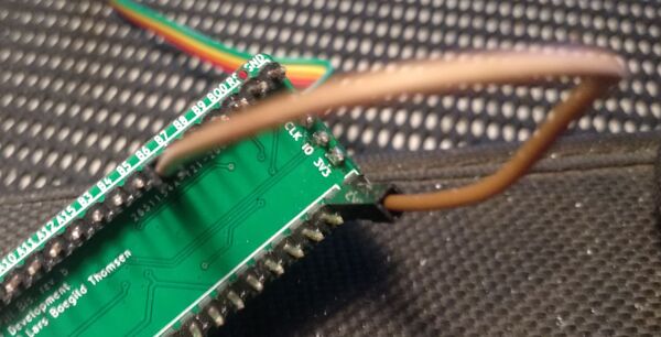
The final approach to blinking a LED would be to use PWM (Pulse-width modulation). Unfortunately, the PC13 GPIO port used in the previous examples, is not able to do hardware PWM, so in order to demonstrate this approach, the built-in LED must be hooked up to a GPIO which allow PWM (we'll be using PB6 in this example). By default, PC13 will be in "input" mode (high impedance), so it is a simple matter of running a jumper wire from PC13 to PB6:
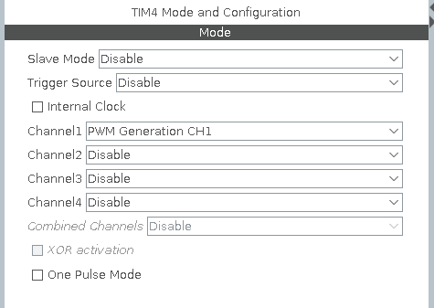
The next step will be to use STM32CubeMX to reconfigure the timer and GPIO pins.
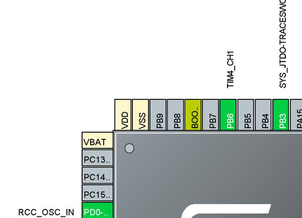
Also remember to reset the PC13 as we want to keep that in high impedance input mode.
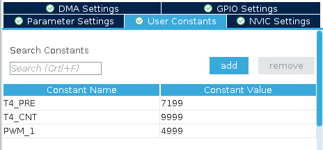
Finally, we need to add an extra "constant" for the PWM duty cycle:
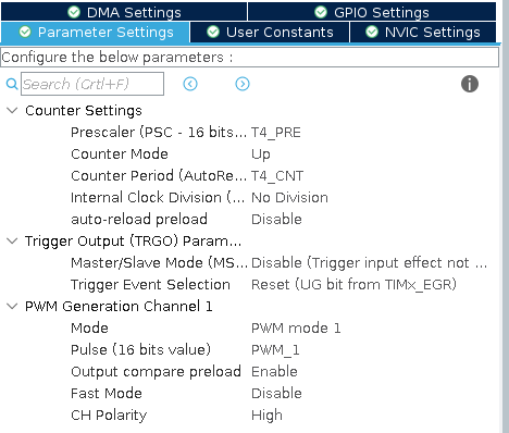
and use that constant as the actual duty cycle:
We are now done with the configuration in Stm32CubeMX and we can generate the code.
In main.c, first we set the constants:
/* USER CODE BEGIN PD */
#define T4_PRE 7199
#define T4_CNT 9999
#define PWM_1 4999
/* USER CODE END PD */
It is now a simple matter of starting the timer in PWM mode:
  /* USER CODE BEGIN 2 */

  // Start the timer in PWM mode - output will be on PB6
  HAL_TIM_PWM_Start(&htim4, TIM_CHANNEL_1);

  /* USER CODE END 2 */
And that is about it - not a single CPU cycle is "wasted" on flashing the LED. It runs entirely in the peripheral hardware.
You can find this example here: https://github.com/lbthomsen/greenpill/tree/master/blink4
LL (Low Level)
The examples in the previous section all used ST's HAL (Hardware Abstraction) Library. These libraries are quite complex and they do take a lot of memory. The HAL library is build on top of some more hardware specific low level libraries known as LL. Fortunately, even with STM32CubeMX, it is possible to avoid the HAL library and stick exclusively with the low level.
Common Settings
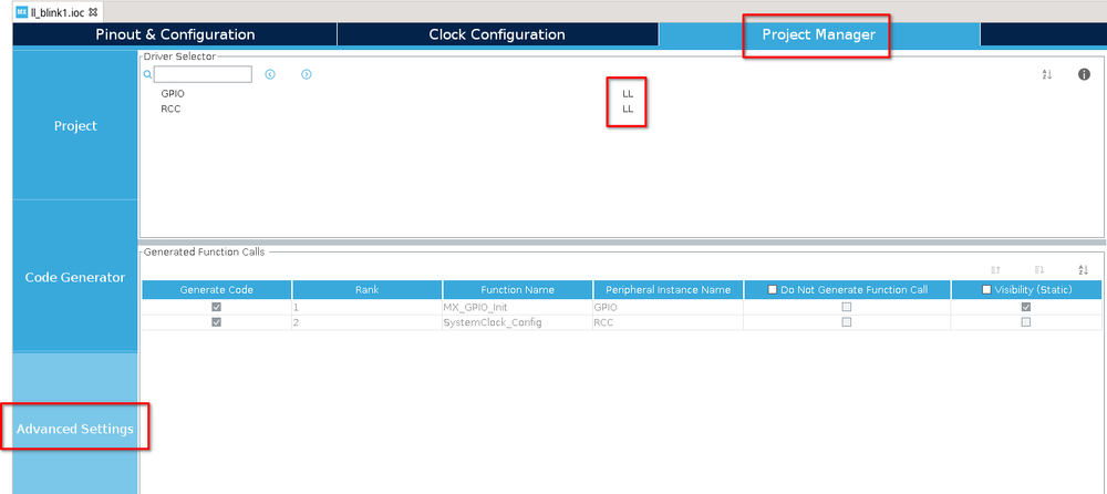
Like the earlier HAL examples, the starting point of the LL examples is STM32CubeMX. This time however, we switch the library from HAL to LL:
Main Loop Without Delay
In principle this works almost exactly like the HAL example. The main difference is that we need to do a bit of housekeeping to maintain the counter.
First step is to enable the systick interrupt.
  /* USER CODE BEGIN 2 */

  // By default LL SysTick interrupt is not enabled - let's enable it
  LL_SYSTICK_EnableIT();

  /* USER CODE END 2 */
The interrupt handler is already defined in `stm32f4xx_it.c`. We just add a counter:
/* USER CODE BEGIN PV */

// Incremented by 1 ms systick interrupt
uint32_t systick_counter = 0;

/* USER CODE END PV */

......

void SysTick_Handler(void)
{
  /* USER CODE BEGIN SysTick_IRQn 0 */

  // Just increase the systick variable
  systick_counter++;

  /* USER CODE END SysTick_IRQn 0 */

  /* USER CODE BEGIN SysTick_IRQn 1 */

  /* USER CODE END SysTick_IRQn 1 */
}
Finally we create a helper function to get this variable. In `stm32f4xx_it.h`
/* USER CODE BEGIN EFP */

uint32_t get_systick_counter();

/* USER CODE END EFP */
And in `stm32f4xx_it.c`:
/* USER CODE BEGIN 1 */

uint32_t get_systick_counter() {
	// Return current value of systick_counter variable
	return systick_counter;
}

/* USER CODE END 1 */
We now, like when using HAL, got a systick counter which increments every 1ms and our main program loop can be implemented like this:
  /* USER CODE BEGIN WHILE */

  uint32_t then = 0, now = 0;

  for (;;)
  {

	  now = get_systick_counter();
	  if (now - then >= 500) {
		  LL_GPIO_TogglePin(LED_GPIO_Port, LED_Pin);
		  then = now;
	  }

    /* USER CODE END WHILE */

    /* USER CODE BEGIN 3 */
  }
  /* USER CODE END 3 */
You can find this example here: https://github.com/lbthomsen/blackpill/tree/master/ll_blink1
Timer Interrupt
Like in the previous example Using a timer, a periodic timer interrupt can be used to toggle the LED on and off.
First, configure the TIM4 exactly like in the previous example, but ensure the advanced config is switched to LL rather than HAL.
While HAL provides a functioning interrupt handler, LL just provide an empty function, so first step is to modify this in `stm32f4xx_it.c`:
void TIM4_IRQHandler(void)
{
  /* USER CODE BEGIN TIM4_IRQn 0 */

	LL_TIM_ClearFlag_UPDATE(TIM4);

	tim4_interrupt_callback();

  /* USER CODE END TIM4_IRQn 0 */
  /* USER CODE BEGIN TIM4_IRQn 1 */

  /* USER CODE END TIM4_IRQn 1 */
}
Essentially we just need to clear the flag so that the MCU know we have handled the interrupt.
In `main.c` we create our callback function:
/* USER CODE BEGIN 0 */

void tim4_interrupt_callback() {
  LL_GPIO_TogglePin(LED_GPIO_Port, LED_Pin);
}

/* USER CODE END 0 */
Now we can start the counter and enable the interrupt:
  /* USER CODE BEGIN 2 */

  LL_TIM_EnableCounter(TIM4);
  LL_TIM_EnableIT_UPDATE(TIM4);

  /* USER CODE END 2 */
And that is it - the LED is happily flashing once per second.
You can find this example here: https://github.com/lbthomsen/blackpill/tree/master/ll_blink2
