Difference between revisions of "STM32 CAN"
Jump to navigation
Jump to search
| Line 19: | Line 19: | ||
[[File:Can loopback example pinout.png]] | [[File:Can loopback example pinout.png]] | ||
</div> | </div> | ||
| + | |||
| + | We can now configure the CAN1 periopheral: | ||
| + | |||
| + | {| | ||
| + | |- | ||
| + | | [[File:Can loopback example can1.png]] | ||
| + | | [[File:Can loopback example can nvic.png]] | ||
| + | |} | ||
== Miscellaneous Links == | == Miscellaneous Links == | ||
To be added | To be added | ||
Revision as of 12:18, 22 December 2023
Introduction
Most STM32 MCUs are equipped with one or more CAN peripherals.
Loopback Example
CubeMX Config
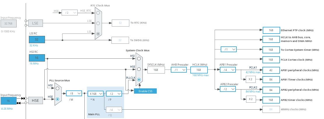
The clock is configured to maximum speed using the external crystal:
Notice the APB1 bus is running at 42 MHz. The CAN peripherals are connected to this bus.
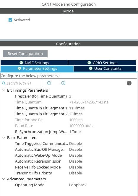
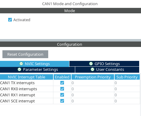
We can now configure the CAN1 periopheral:

|

|
Miscellaneous Links
To be added

