CAN bus
A controller area network (CAN bus) is a vehicle bus standard designed to allow microcontrollers and devices to communicate with each other's applications without a host computer. It is a message-based protocol, designed originally for multiplex electrical wiring within automobiles to save on copper, but it can also be used in many other contexts. For each device, the data in a frame is transmitted serially but in such a way that if more than one device transmits at the same time, the highest priority device can continue while the others back off. Frames are received by all devices, including by the transmitting device.
Bus Layout
A CAN bus consist of a differential set of wires with a number of nodes attached in parallel.
The wires operate in differential mode to suppress noise.
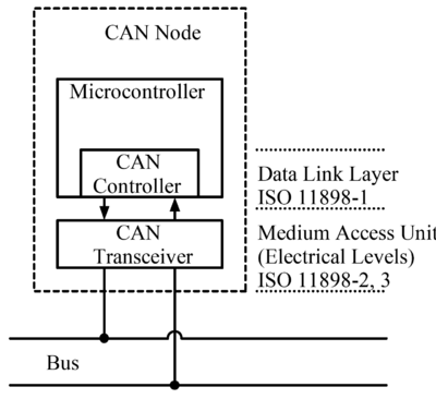
The nodes themselves consist of a CAN Controller and a transceiver which will adjust the signals to match the bus:
Multi Master
The exact voltages for a logical 0 or 1 depend on the physical layer used, but the basic principle of CAN requires that each node listen to the data on the CAN network including the transmitting node(s) itself (themselves). If a logical 1 is transmitted by all transmitting nodes at the same time, then a logical 1 is seen by all of the nodes, including both the transmitting node(s) and receiving node(s). If a logical 0 is transmitted by all transmitting node(s) at the same time, then a logical 0 is seen by all nodes. If a logical 0 is being transmitted by one or more nodes, and a logical 1 is being transmitted by one or more nodes, then a logical 0 is seen by all nodes including the node(s) transmitting the logical 1. When a node transmits a logical 1 but sees a logical 0, it realizes that there is a contention and it quits transmitting. By using this process, any node that transmits a logical 1, when another node transmits a logical 0, loses the arbitration and drops out. A node that loses arbitration re-queues its message for later transmission and the CAN frame bit-stream continues without error until only one node is left transmitting. This means that the node that transmits the first 1 loses arbitration. Since the 11 (or 29 for CAN 2.0B) bit identifier is transmitted by all nodes at the start of the CAN frame, the node with the lowest identifier transmits more zeros at the start of the frame, and that is the node that wins the arbitration or has the highest priority.
For example, consider an 11-bit ID CAN network, with two nodes with IDs of 15 (binary representation, 00000001111) and 16 (binary representation, 00000010000). If these two nodes transmit at the same time, each will first transmit the start bit then transmit the first six zeros of their ID with no arbitration decision being made.
| Start bit |
ID bits | The rest of the frame | |||||||||||
|---|---|---|---|---|---|---|---|---|---|---|---|---|---|
| 10 | 9 | 8 | 7 | 6 | 5 | 4 | 3 | 2 | 1 | 0 | |||
| Node 15 | 0 | 0 | 0 | 0 | 0 | 0 | 0 | 0 | 1 | 1 | 1 | 1 | |
| Node 16 | 0 | 0 | 0 | 0 | 0 | 0 | 0 | 1 | Stopped Transmitting | ||||
| CAN data | 0 | 0 | 0 | 0 | 0 | 0 | 0 | 0 | 1 | 1 | 1 | 1 | |
When ID bit 4 is transmitted, the node with the ID of 16 transmits a 1 (recessive) for its ID, and the node with the ID of 15 transmits a 0 (dominant) for its ID. When this happens, the node with the ID of 16 knows it transmitted a 1, but sees a 0 and realizes that there is a collision and it lost arbitration. Node 16 stops transmitting which allows the node with ID of 15 to continue its transmission without any loss of data. The node with the lowest ID will always win the arbitration and therefore has the highest priority.
CAN Frame
The frame format is as follows: The bit values are described for CAN-LO signal.
| Field name | Length (bits) | Purpose |
|---|---|---|
| Start-of-frame | 1 | Denotes the start of frame transmission |
| Identifier (green) | 11 | A (unique) identifier which also represents the message priority |
| Remote transmission request (RTR) (blue) | 1 | Must be dominant (0) for data frames and recessive (1) for remote request frames (see Remote Frame, below) |
| Identifier extension bit (IDE) | 1 | Must be dominant (0) for base frame format with 11-bit identifiers |
| Reserved bit (r0) | 1 | Reserved bit. Must be dominant (0), but accepted as either dominant or recessive. |
| Data length code (DLC) (yellow) | 4 | Number of bytes of data (0–8 bytes) |
| Data field (red) | 0–64 (0-8 bytes) | Data to be transmitted (length in bytes dictated by DLC field) |
| CRC | 15 | Cyclic redundancy check |
| CRC delimiter | 1 | Must be recessive (1) |
| ACK slot | 1 | Transmitter sends recessive (1) and any receiver can assert a dominant (0) |
| ACK delimiter | 1 | Must be recessive (1) |
| End-of-frame (EOF) | 7 | Must be recessive (1) |
| Inter-frame spacing (IFS) | 3 | Must be recessive (1) |
As can be seen the overhead is massive. 47 bit required to send a maximum of a 64 bit payload. The CAN bus is definitely not designed for speed but rather reliability.


