Difference between revisions of "MIDItio"
(→MCU) |
|||
| (15 intermediate revisions by the same user not shown) | |||
| Line 1: | Line 1: | ||
[[Category:Awesome Audio Apparatus]][[Category:STM32 Projects]][[Category:Work in progress]]{{metadesc|USB Midi to CV}} | [[Category:Awesome Audio Apparatus]][[Category:STM32 Projects]][[Category:Work in progress]]{{metadesc|USB Midi to CV}} | ||
| − | [[File:MIDItio rendering - top view.png|200px|thumb|MIDItio Rendering]] | + | [[File:MIDItio rev. a rendering - top view.png|200px|thumb|MIDItio Rendering]] |
[[MIDItio]] is a [[:Category:Work in progress|planned]] USB Midi to CV device. The device will act as a USB MIDI device connected to a USB host. It will be able to run two channels simultaneously with a CV indicating the pitch and a Gate indicating start and stop. | [[MIDItio]] is a [[:Category:Work in progress|planned]] USB Midi to CV device. The device will act as a USB MIDI device connected to a USB host. It will be able to run two channels simultaneously with a CV indicating the pitch and a Gate indicating start and stop. | ||
The name [[MIDItio]] is derived from [[MIDI]] and the Latin "ditio" which means "control". | The name [[MIDItio]] is derived from [[MIDI]] and the Latin "ditio" which means "control". | ||
| + | |||
| + | Planned features are: | ||
| + | |||
| + | * USB MIDI Gadget/Device | ||
| + | * 2 MIDI channels | ||
| + | * Dual pitch CV output (1V/oct) | ||
| + | * Dual gate output | ||
| + | * 5 octave range (0V - 5V) | ||
| + | * Self calibration | ||
| + | |||
| + | The [[MIDItio]] device has got two analog outputs (CV) and two digital outputs (gate). It can be configured to run in two different "modes": | ||
| + | |||
| + | # Two channel pitch and gate | ||
| + | # One channel pitch, velocity and gate | ||
| + | |||
| + | When operating in two channel mode, the velocity is ignored. | ||
== Hardware Design == | == Hardware Design == | ||
| Line 9: | Line 25: | ||
== MCU == | == MCU == | ||
| − | The | + | The primary concerns dictating the choice of [[MCU]] are: |
# Built-in USB | # Built-in USB | ||
| − | # Built-in | + | # Built-in Digital to Analogue converters (DAC) - preferably 2 |
| + | |||
| + | # Cost | ||
| + | |||
| + | The [[STM32L151]] fits the bill nicely. | ||
=== Output Amplifier === | === Output Amplifier === | ||
| − | Without a boost regulator the highest available voltage on the board is the USB VBUS 5V. | + | Without a boost regulator the highest available voltage on the board is the USB VBUS 5V. That means the output amplifier for the CV's need to map 0-3.3V into 0-5V. |
| + | |||
| + | A = 5 / 3.3. = 1.515 | ||
| + | |||
| + | The amplification of a non-inverting opamp is: | ||
| + | |||
| + | A = 1 + Rf / R2 | ||
| + | |||
| + | If we choose R2 = 9.1 kΩ, we can calculate Rf | ||
| + | |||
| + | Rf = (A - 1) * R2 = 0.515 * 9.1 kΩ = 4.68 kΩ | ||
| + | |||
| + | A Rf of 4.7 kΩ should do nicely. | ||
| + | |||
| + | === Self calibration === | ||
| + | |||
| + | The output amplifier will add a certain DC error (due to tolerances on the resistors) and we'll need a way to calibrate the device. In our case we simply feed the amplified output back to an ADC. The input pins on STM32 are 5V tolerant when in digital mode, but when set to analogue they are ''not''! So some care should be taken not to set the value higher than 3.3 V while calibrating. | ||
| + | |||
| + | The internal voltage reference in the STM32 is quite poor, so we have also added a 0.1 % voltage reference. That way we can compare the measured values of the DAC's with this voltage reference and adjust for any errors. | ||
=== Schematics === | === Schematics === | ||
| Line 23: | Line 61: | ||
<div class="res-img"> | <div class="res-img"> | ||
[[File:MIDItio rev. a schematic.svg|2400px]] | [[File:MIDItio rev. a schematic.svg|2400px]] | ||
| + | </div> | ||
| + | |||
| + | === Renderings === | ||
| + | |||
| + | <gallery> | ||
| + | File:MIDItio Rendering with cover.png | ||
| + | File:MIDItio rendering without cover.png | ||
| + | </gallery> | ||
| + | |||
| + | == Prototype rev a == | ||
| + | |||
| + | === Gallery === | ||
| + | |||
| + | First prototype was ordered and this is how they turned out: | ||
| + | |||
| + | <gallery> | ||
| + | File:MIDItio rev. a - five plus cover.jpg | ||
| + | File:MIDItio rev a plus cover.jpg | ||
| + | File:MIDItio rev. a with cover.jpg | ||
| + | File:MIDItio buttons.jpg | ||
| + | </gallery> | ||
| + | |||
| + | === Testing === | ||
| + | |||
| + | After receiving the rev. a prototype a few things became immediately obvious. First of all, the stm32l151 USB is gadget/device only and thus do not have a built-in pull up on the D+ line. Second, the stm32l151 does not have DFU support in it's built-in bootloader. | ||
| + | |||
| + | The first was easily tested with a bodge resistor: | ||
| + | |||
| + | [[File:MIDItio usb d+ bodge.jpg|400px]] | ||
| + | |||
| + | I did not have a 1.5 k resistor lying around, so I used a 2 k one and that works fine. | ||
| + | |||
| + | == Revision b == | ||
| + | |||
| + | Based on the testing a few changes was made for revision b. | ||
| + | |||
| + | # 1.5 k pull-up resistor on USB D+ line | ||
| + | # B0 no longer connected to Boot0 | ||
| + | # Additional filtering of VDDA | ||
| + | |||
| + | <div class="res-img"> | ||
| + | [[File:MIDItio rev. b schematics.svg|1800px]] | ||
| + | </div> | ||
| + | |||
| + | == Firmware == | ||
| + | |||
| + | === STM32 Pin Assignment === | ||
| + | |||
| + | The pin assignment is pretty straight forward, largely dictated by the analog pins and how they are wired together in the schematics. | ||
| + | |||
| + | <div class="res-img"> | ||
| + | [[File:MIDItio Pin Assignment.png|600px]] | ||
</div> | </div> | ||
| Line 31: | Line 121: | ||
* [https://datasheet.lcsc.com/lcsc/1810251030_STMicroelectronics-STM32L151C8T6_C9861.pdf STM32L151 Datasheet] | * [https://datasheet.lcsc.com/lcsc/1810251030_STMicroelectronics-STM32L151C8T6_C9861.pdf STM32L151 Datasheet] | ||
* [https://www.st.com/resource/en/reference_manual/rm0038-stm32l100xx-stm32l151xx-stm32l152xx-and-stm32l162xx-advanced-armbased-32bit-mcus-stmicroelectronics.pdf STM32L151 Reference Manual] | * [https://www.st.com/resource/en/reference_manual/rm0038-stm32l100xx-stm32l151xx-stm32l152xx-and-stm32l162xx-advanced-armbased-32bit-mcus-stmicroelectronics.pdf STM32L151 Reference Manual] | ||
| + | * [https://github.com/Hypnotriod/midi-box-stm32 STM32 HAL MIDI device example] | ||
Latest revision as of 03:52, 7 September 2022
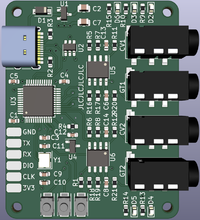
MIDItio is a planned USB Midi to CV device. The device will act as a USB MIDI device connected to a USB host. It will be able to run two channels simultaneously with a CV indicating the pitch and a Gate indicating start and stop.
The name MIDItio is derived from MIDI and the Latin "ditio" which means "control".
Planned features are:
- USB MIDI Gadget/Device
- 2 MIDI channels
- Dual pitch CV output (1V/oct)
- Dual gate output
- 5 octave range (0V - 5V)
- Self calibration
The MIDItio device has got two analog outputs (CV) and two digital outputs (gate). It can be configured to run in two different "modes":
- Two channel pitch and gate
- One channel pitch, velocity and gate
When operating in two channel mode, the velocity is ignored.
Hardware Design
MCU
The primary concerns dictating the choice of MCU are:
- Built-in USB
- Built-in Digital to Analogue converters (DAC) - preferably 2
- Cost
The STM32L151 fits the bill nicely.
Output Amplifier
Without a boost regulator the highest available voltage on the board is the USB VBUS 5V. That means the output amplifier for the CV's need to map 0-3.3V into 0-5V.
A = 5 / 3.3. = 1.515
The amplification of a non-inverting opamp is:
A = 1 + Rf / R2
If we choose R2 = 9.1 kΩ, we can calculate Rf
Rf = (A - 1) * R2 = 0.515 * 9.1 kΩ = 4.68 kΩ
A Rf of 4.7 kΩ should do nicely.
Self calibration
The output amplifier will add a certain DC error (due to tolerances on the resistors) and we'll need a way to calibrate the device. In our case we simply feed the amplified output back to an ADC. The input pins on STM32 are 5V tolerant when in digital mode, but when set to analogue they are not! So some care should be taken not to set the value higher than 3.3 V while calibrating.
The internal voltage reference in the STM32 is quite poor, so we have also added a 0.1 % voltage reference. That way we can compare the measured values of the DAC's with this voltage reference and adjust for any errors.
Schematics
Renderings
Prototype rev a
Gallery
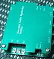
First prototype was ordered and this is how they turned out:
Testing
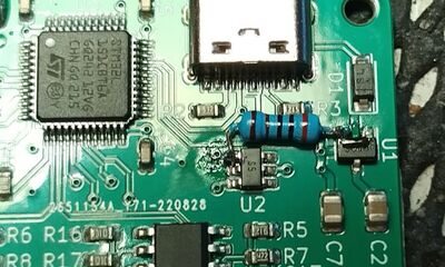
After receiving the rev. a prototype a few things became immediately obvious. First of all, the stm32l151 USB is gadget/device only and thus do not have a built-in pull up on the D+ line. Second, the stm32l151 does not have DFU support in it's built-in bootloader.
The first was easily tested with a bodge resistor:
I did not have a 1.5 k resistor lying around, so I used a 2 k one and that works fine.
Revision b
Based on the testing a few changes was made for revision b.
- 1.5 k pull-up resistor on USB D+ line
- B0 no longer connected to Boot0
- Additional filtering of VDDA
Firmware
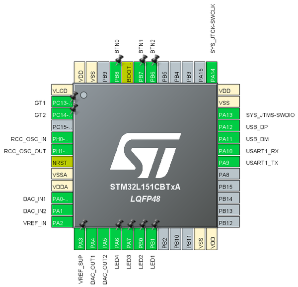
STM32 Pin Assignment
The pin assignment is pretty straight forward, largely dictated by the analog pins and how they are wired together in the schematics.


