Difference between revisions of "Stm32Dev - rev. b"
| Line 14: | Line 14: | ||
The reasoning behind these choices should be pretty darn obvious, but let me go through them anyway. | The reasoning behind these choices should be pretty darn obvious, but let me go through them anyway. | ||
| − | [[File:Jumper leads on headers.jpg|thumb|Jumper leads on headers]]I absolutely positively despise breadboards. True, I might have had bad experiences because my breadboards were cheap crap, but I find myself spending more time chasing down lose connections than I do doing anything productive, so I generally much prefer just to wire stuff up using jumper leads directly on the headers. | + | [[File:Jumper leads on headers.jpg|thumb|Jumper leads on headers]]I absolutely positively despise breadboards. True, I might have had bad experiences because my breadboards were cheap crap, but I find myself spending more time chasing down lose connections than I do doing anything productive, so I generally much prefer just to wire stuff up using jumper leads directly on the headers. By using that approach I regularly end up in a situation where I need two leads connected to one pin, hence having a dual row is convenient. |
| + | |||
| + | The [[LDO]] on the original board was massively over dimensioned (can handle up to 1-2 amps). Switched that to a [https://lcsc.com/product-detail/Dropout-Regulators-LDO_Torex-Semicon-XC6206P332MR_C5446.html Torex Semicon XC6206P332MR] which will happily handle the 500 mA possible from a [[USB]] port. | ||
| + | |||
| + | Having the buttons is just a massive convenience on a development board. | ||
| + | |||
| + | |||
== Schematics == | == Schematics == | ||
Revision as of 03:43, 25 November 2020
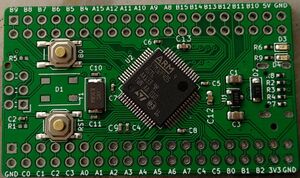
When designing the Stm32Dev - first version a number of mistakes was made. This lead naturally to the development of Stm32Dev - rev. b.
While the overall design is identical to the first version, a number of tweaks were made. These include:
- Double headers
- Different choice of LDO
- Buttons for NRST and Boot0
- 8 MHz Crystal
- Regular blue LED on PC13
- WS2812B hanging off of PC6
The reasoning behind these choices should be pretty darn obvious, but let me go through them anyway.
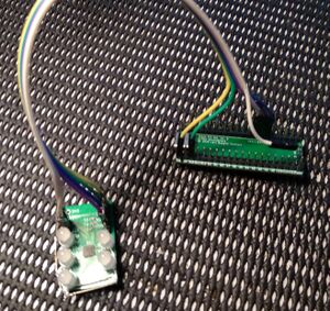
I absolutely positively despise breadboards. True, I might have had bad experiences because my breadboards were cheap crap, but I find myself spending more time chasing down lose connections than I do doing anything productive, so I generally much prefer just to wire stuff up using jumper leads directly on the headers. By using that approach I regularly end up in a situation where I need two leads connected to one pin, hence having a dual row is convenient.
The LDO on the original board was massively over dimensioned (can handle up to 1-2 amps). Switched that to a Torex Semicon XC6206P332MR which will happily handle the 500 mA possible from a USB port.
Having the buttons is just a massive convenience on a development board.
Schematics
The full schematics is as:


