Uncategorized files
Jump to navigation
Jump to search
Showing below up to 363 results in range #501 to #863.
View (previous 500 | next 500) (20 | 50 | 100 | 250 | 500)
 EEPROM Footprint Documentation.png 1,035 × 391; 46 KB
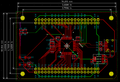
 ESC Pinout Test.png 750 × 711; 137 KB
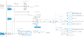
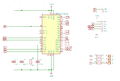
 ESP32-2424s012 Schematics.png 1,328 × 862; 569 KB
 Empty.png 704 × 396; 142 bytes
 Empty Flash.png 1,154 × 901; 160 KB
 Encoder Timer interrupt.png 488 × 100; 7 KB
 Encoder parameter settings.png 488 × 525; 18 KB
 Error.png 553 × 270; 16 KB
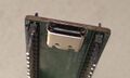
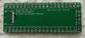
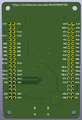
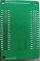
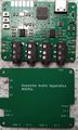
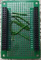
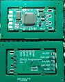
 Extension Board without module.jpg 3,701 × 2,804; 1.54 MB
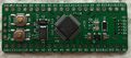
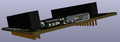
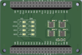
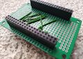
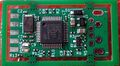
 Extension board w. module.jpg 3,799 × 2,644; 1.48 MB
 FK Clock.png 1,380 × 733; 68 KB
 FidoKey rev. a - top view.jpg 1,352 × 445; 129 KB
 File - New project.png 701 × 380; 43 KB
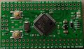
 First STM32 Development Board.jpg 1,912 × 1,496; 318 KB
 Fk2.svg 1,052 × 744; 408 KB
 Flash button.png 88 × 80; 3 KB
 Flip Side USB-C Connector.jpg 1,298 × 780; 81 KB
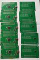
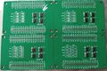 Four MEM24CXX without headers.jpg 3,510 × 2,331; 1.23 MB
 FreeRTOS Middleware.png 195 × 583; 7 KB
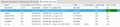 FreeRTOS Task List.png 1,091 × 249; 50 KB
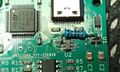
 GD32E103CB close up.jpg 698 × 653; 206 KB
 GD32F103 - close up.JPG 1,602 × 1,329; 408 KB
 GD32F405 Architecture.png 625 × 902; 124 KB
 GD32F4xx Bootmodes from datasheet.png 715 × 316; 44 KB
 GD32F4xx Bootmodes from user manual.png 637 × 99; 16 KB
 GD32VF103 options.png 967 × 585; 65 KB
 GD405 timer 4.png 498 × 684; 22 KB
 GD Menu.png 269 × 406; 18 KB
 Games.png 1,062 × 839; 512 KB
 Green Pill - gd32 variant - btm side.jpg 1,353 × 566; 151 KB
 Green Pill - gd32 variant - top side.jpg 1,353 × 543; 160 KB
 Green Pill - gd32f103 variant.JPG 5,152 × 1,897; 1.55 MB
 Green Pill as JTAG adapter.jpg 3,336 × 2,447; 499 KB
 Green Pill rev. a - btm side.jpg 2,039 × 991; 369 KB
 Green Pill rev. a - top side.jpg 2,182 × 983; 430 KB
 Green Pill rev. b - btm side.jpg 1,647 × 741; 226 KB
 Green Pill rev. b - fully assembled.jpg 2,350 × 1,728; 379 KB
 Green Pill rev. b - top side.jpg 1,681 × 741; 294 KB
 Green Pill rev. c.svg 1,052 × 744; 461 KB
 Green Pill rev. c - fully assembled top view.jpg 3,081 × 1,241; 709 KB
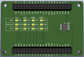
 I-O Board - bot.jpg 2,514 × 949; 160 KB
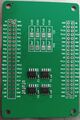
 I-O Board - top.jpg 2,529 × 949; 308 KB
 I2C Configuration.png 733 × 617; 27 KB
 I2C Connection.jpg 2,577 × 2,554; 453 KB
 I2C Play Clock Settings.png 1,114 × 543; 35 KB
 I2C bit stream.png 725 × 175; 26 KB
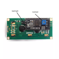 I2C extender on LCD display.webp 900 × 900; 33 KB
 I2c Config.png 516 × 627; 18 KB
 I2c Module to LCD.png 1,075 × 480; 68 KB
 ICESugar-v1.5 schematic.png 2,337 × 1,652; 581 KB
 ICESugar Original Pinout.webp 1,200 × 800; 127 KB
 IMG 20200716 111342.jpg 3,132 × 1,687; 1.32 MB
 IMG 20200716 111401.jpg 2,039 × 991; 369 KB
 IMG 20200716 111414.jpg 2,182 × 983; 430 KB
 IMG 20200717 124537.jpg 3,214 × 1,644; 1.55 MB
 IMG 20200718 101738.jpg 1,414 × 800; 212 KB
 IMG 20200718 101745.jpg 1,403 × 981; 268 KB
 IMG 20200719 185648.jpg 1,509 × 1,197; 289 KB
 IMG 20200721 112832.jpg 4,000 × 3,000; 344 KB
 IMG 20200724 102325.jpg 3,800 × 2,072; 1.64 MB
 IMG 20200724 102327.jpg 3,871 × 2,166; 1.7 MB
 IMG 20200724 102345.jpg 1,610 × 3,004; 1.1 MB
 IMG 20200724 102349.jpg 1,525 × 2,844; 1.05 MB
 IMG 20200724 102412.jpg 1,681 × 741; 294 KB
 IMG 20200724 102421.jpg 1,546 × 712; 232 KB
 IMG 20200724 102425.jpg 1,647 × 741; 226 KB
 IMG 20200724 170838.jpg 2,350 × 1,728; 379 KB
 IMG 20200724 170852.jpg 2,078 × 1,606; 260 KB
 IMG 20200724 172406.jpg 2,591 × 1,302; 439 KB
 IMG 20200726 123135.jpg 3,338 × 1,305; 515 KB
 IMG 20200726 133329.jpg 946 × 1,914; 286 KB
 IMG 20200812 104552.jpg 840 × 1,050; 55 KB
 IMG 20200812 104604.jpg 1,814 × 2,362; 700 KB
 IMG 20200812 104716.jpg 1,979 × 1,385; 418 KB
 IMG 20230829 093739.jpg 1,400 × 514; 162 KB
 IMG 20230829 093825.jpg 1,381 × 1,159; 422 KB
 IMG 20230829 093840.jpg 1,268 × 325; 124 KB
 IMG 20230829 093913.jpg 1,255 × 286; 70 KB
 IMG 20230829 094004.jpg 1,241 × 424; 109 KB
 IMG 20240409 162321.jpg 695 × 927; 104 KB
 IOAW9523 3D Top View rendering.png 1,323 × 819; 113 KB
 IOAW9523 rendering.png 1,189 × 706; 105 KB
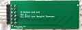
 IO Button LED schematics.png 728 × 830; 14 KB
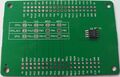
 IO Button and LED - top view.jpg 2,529 × 949; 308 KB
 ITG-3200 I2C address.png 828 × 123; 32 KB
 Iot flash.png 1,376 × 987; 131 KB
 I²C 7-bit Addresses.png 737 × 187; 26 KB
 JDY-40 Module.jpg 1,003 × 627; 86 KB
 JDY-40 Modules.jpg 2,957 × 1,935; 846 KB
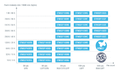
 JLCPCB Assembly Capabilities.png 917 × 518; 65 KB
 JLCPCB STM32F405.png 1,219 × 433; 212 KB
 Jumper leads on headers.jpg 2,625 × 2,479; 1.04 MB
 Kowtktu2vi9ap5goa63raqw6igyyyv5.jpg 1,356 × 791; 202 KB
 LD23410c Top View.webp 800 × 800; 60 KB
 LD2410c Top View.png 800 × 800; 468 KB
 LFE5U-25F-8BG381C.pdf ; 3.03 MB
 Ledctl1.png 1,328 × 722; 273 KB
 Ledctl2.png 1,146 × 745; 200 KB
 Ledctl3.png 1,340 × 688; 142 KB
 Ledctl4.png 1,579 × 748; 217 KB
 Ledctl rev a.svg 1,052 × 744; 393 KB
 Ledctl rev c.svg 1,052 × 744; 445 KB
 Logo.jpg 480 × 462; 94 KB
 Logo.png 180 × 173; 52 KB
 Longan nano pinout v1.1.0 w5676 h4000 large.png 2,048 × 1,443; 1.06 MB
 M1s doc pin map.png 1,239 × 1,050; 871 KB
 M1s module outlook.png 480 × 379; 349 KB
 M2-expansion-1.jpg 3,000 × 4,000; 443 KB
- M2-expansion-E-RevA-pcb.pdf ; 65 KB
 MAX7219 Typical Application Circuit.png 552 × 473; 47 KB
 MCUSTM32F103 3D Top View.png 1,324 × 877; 141 KB
 MCUSTM32F103 3D Top View 2.png 1,329 × 884; 150 KB
 MCUSTM32F405 3D Top View.png 1,296 × 875; 147 KB
 MCUSTM32F405 Bot.jpg 2,789 × 1,800; 687 KB
 MCUSTM32F405 Rendering 1.png 1,452 × 512; 105 KB
 MCUSTM32F405 Rendering 2.png 594 × 872; 116 KB
 MCUSTM32F405 Top.jpg 2,773 × 1,779; 739 KB
 MCUSTM32F405 and MEMW25Q128.jpg 2,675 × 4,000; 2.47 MB
 MCUSTM32F405 angle.jpg 3,847 × 2,186; 945 KB
 MCUSTM32F405 with headers.jpg 3,149 × 2,104; 1.02 MB
 MCUSTM32F411 3D Top View.png 968 × 635; 100 KB
 MCUSTM32F446 3D rendering - top view.png 1,067 × 702; 126 KB
 MCUSTM32F446 rev. a schematics.svg 1,052 × 744; 781 KB
 MEM24CXX Bottom View.jpg 1,992 × 3,015; 534 KB
 MEM24CXX Rendering Top.png 1,141 × 762; 101 KB
 MEM24CXX Sandwiched Between Programmer and MCU.jpg 2,773 × 2,618; 825 KB
 MEM24CXX Stacked with programmer and mcu.jpg 3,072 × 2,577; 737 KB
 MEM24CXX Top View.jpg 2,009 × 3,014; 665 KB
 MEMW25Q128 3D Top View rendering.png 1,257 × 851; 108 KB
 MEMW25Q128 Bot.jpg 3,233 × 2,021; 831 KB
 MEMW25Q128 Top.jpg 3,293 × 2,124; 859 KB
 MEMW25Q128 wiith headers.jpg 3,067 × 2,001; 608 KB
 MIDItio Pin Assignment.png 742 × 714; 86 KB
 MIDItio Rendering with cover.png 946 × 610; 71 KB
 MIDItio buttons.jpg 1,593 × 1,754; 377 KB
 MIDItio rendering without cover.png 965 × 668; 232 KB
 MIDItio rev. a - five plus cover.jpg 2,810 × 2,233; 1.24 MB
 MIDItio rev. a rendering - top view.png 776 × 853; 162 KB
 MIDItio rev. a schematic.svg 1,052 × 744; 594 KB
 MIDItio rev. a with cover.jpg 1,620 × 1,311; 257 KB
 MIDItio rev. b schematics.svg 1,052 × 744; 577 KB
 MIDItio rev a plus cover.jpg 1,552 × 2,581; 663 KB
 MIDItio usb d+ bodge.jpg 1,125 × 674; 198 KB
 MMC-SD-miniSD-microSD-Color-Numbers-Names.gif 384 × 698; 18 KB
 MMC-SD-miniSD-microSD-Color-Numbers-Names.png 384 × 698; 17 KB
 MPR121 Keypad.svg 1,052 × 744; 286 KB
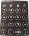 MPR121 Keypad rev. b.jpg 2,504 × 3,027; 655 KB
 MPR121 Keypad rev. b - bot.jpg 1,346 × 1,594; 168 KB
 MPR121 Keypad rev. b schematics.svg 1,052 × 744; 285 KB
 MPR121 components.jpg 2,155 × 625; 164 KB
 MPR121 rev. b hooked up.jpg 2,260 × 3,226; 1.34 MB
 Magic Key and Display.jpg 3,413 × 1,710; 696 KB
 Magic Key rendering - bottom view.png 781 × 562; 90 KB
 Magic Key rendering - top view.png 514 × 639; 58 KB
 Makefile Tools.png 664 × 175; 24 KB
 Mcu board 3d.png 1,028 × 624; 86 KB
 Mcu flash.png 1,376 × 987; 145 KB
 Mcustm32f405 schematics.svg 1,052 × 744; 829 KB
 Mem24cxx.svg 1,052 × 744; 823 KB
 Memw25q128 schematics.svg 1,052 × 744; 425 KB
 More GPS.png 1,088 × 444; 208 KB
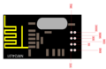
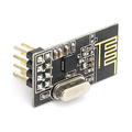 NRF24L01 Module.png 600 × 600; 273 KB
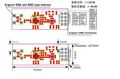
 NRF24L01 Module Pinout.png 616 × 400; 29 KB
 Nrf24l01+ amplified external antenna.jpg 704 × 464; 78 KB
 Nrf24l01+ module dimensions.jpg 700 × 577; 69 KB
 Nrf24l01+ module with external antenna.jpg 3,200 × 1,135; 641 KB
 One shot timer.png 734 × 761; 31 KB
 Option Bytes Before.png 1,154 × 901; 159 KB
 Option byte back.png 1,154 × 901; 146 KB
 Ox64-cores.jpg 1,993 × 1,273; 204 KB
 Ox64 pinout.png 2,500 × 1,625; 383 KB
 PC13 to PB6 jumper.jpg 2,899 × 1,479; 459 KB
 PCB Layout rev. a.png 1,158 × 687; 64 KB
 PCB Layout rev. a - 3D model.png 1,779 × 736; 219 KB
 PRGSTL 3D Top View.png 1,312 × 875; 168 KB
 PRGSTL Bot.jpg 2,610 × 1,727; 573 KB
 PRGSTL Side.jpg 3,673 × 2,150; 832 KB
 PRGSTL Top.jpg 2,321 × 1,532; 511 KB
 PRGSTL and MCUSTM32F405.jpg 2,191 × 3,276; 1.32 MB
 PRGSTL with headers.jpg 2,714 × 1,789; 481 KB
 PROTO wired for uart i2c and spi - side view.jpg 4,000 × 2,869; 1.41 MB
 PROTO wired for uart i2c and spi - top view.jpg 1,680 × 2,441; 778 KB
 PWM Input Capture example - Timer 2 confriguration.png 475 × 767; 25 KB
 PWM Input Capture example - Timer 4 configuration.png 483 × 734; 24 KB
 PWM Input Capture example - clock settings.png 1,557 × 602; 45 KB
 PWM Input Capture example - pinout.png 725 × 670; 111 KB
 PWM Input Capture example - timer 2 interrupt.png 487 × 431; 15 KB
 PWM Input Capture example - wiring.jpg 2,557 × 2,762; 1.15 MB
 Pcb layout.png 1,297 × 876; 206 KB
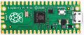 Pico Board.jpg 1,267 × 529; 167 KB
 Prgstl rev a.svg 1,052 × 744; 1.29 MB
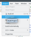 Project-Build.png 271 × 321; 24 KB
 Proto Example Pinout.png 689 × 637; 90 KB
 Proto top rendering.png 1,259 × 842; 338 KB
 Proto top side view.jpg 2,966 × 2,318; 794 KB
 Proto top stacked.jpg 3,495 × 2,724; 1.04 MB
 Proto top view.jpg 1,690 × 2,273; 665 KB
 RDP Level vs. Access.png 808 × 312; 38 KB
 RDP Levels.png 706 × 508; 64 KB
 Real STM32F103.jpg 820 × 701; 170 KB
 Registers at start of main.png 303 × 427; 13 KB
 Rejection.png 1,141 × 391; 53 KB
 Removed from Bing.png 1,243 × 497; 34 KB
 Rendering side view.png 1,575 × 512; 66 KB
 Reset and Boot0.png 789 × 774; 10 KB
 Response 1.png 737 × 221; 38 KB
 Response 2.png 736 × 205; 48 KB
 Rev g bot.jpg 1,333 × 612; 104 KB
 Rev g top.jpg 1,176 × 603; 117 KB
 Rotary Encoder Signals.png 679 × 319; 4 KB
 Rotary Encoder w. debounce circuitry.jpg 1,562 × 1,644; 147 KB
 Rotary debounce.png 1,286 × 785; 79 KB
 Rotary encoder pins.png 416 × 310; 23 KB
 Rotary encoder signals.jpeg 734 × 336; 32 KB
 SPI Configuration.png 716 × 729; 35 KB
 ST-Link-V2-1 Renumeration Circuitry.png 1,037 × 785; 19 KB
 ST-Link Bunch.jpg 2,747 × 2,999; 672 KB
 ST-Link Greenpill connection.jpg 2,887 × 1,319; 651 KB
 ST-Link Upgrade initial flash.png 943 × 315; 74 KB
 ST-Link V2.1 Original Schematics.png 1,529 × 947; 290 KB
 ST-Link V2.png 1,400 × 924; 233 KB
 ST-Link after upgrade.png 943 × 315; 71 KB
 ST-Link connected to Black Pill.jpg 2,498 × 2,444; 1.31 MB
 ST-Link rev. d - btm view.jpg 1,255 × 750; 105 KB
 ST-Link rev. d - top view.jpg 1,345 × 804; 133 KB
 ST-Link rev. d 5 pieces top view.jpg 2,658 × 1,138; 394 KB
 ST7789 1.3 inch display module.webp 743 × 486; 57 KB
 ST7789 Pins.png 679 × 358; 64 KB
 STLink-v2 (Chinese knock off).jpg 427 × 196; 32 KB
 STLink.jpg 3,280 × 2,697; 787 KB
 STM32CubeMX MCU Selector.png 1,274 × 905; 81 KB
 STM32CubeMX New Project.png 342 × 415; 14 KB
 STM32CubeMX Project Manager Config.png 1,434 × 507; 21 KB
 STM32CubeMX USB Config.png 525 × 681; 16 KB
 STM32CubeProgrammer - connection options.png 263 × 185; 12 KB
 STM32CubeProgrammer connected.png 1,244 × 841; 166 KB
 STM32Dev WS2812B RGB LED.jpg 1,275 × 815; 280 KB
 STM32F030 Flash Page Layout.png 942 × 776; 111 KB
 STM32F103 Data Retention.png 737 × 303; 47 KB
 STM32F103 Features Timers.png 464 × 237; 32 KB
 STM32F103 Timers and watchdogs.png 900 × 409; 66 KB
 STM32F103xx Flash Page Layout.png 897 × 796; 102 KB
 STM32F402 on LCSC.png 1,541 × 584; 343 KB
 STM32F407G-DISC1 Top View.png 525 × 806; 835 KB
 STM32F411 Flash Sector Layout.png 695 × 392; 58 KB
 STM32F411 Low Power TOC.png 777 × 254; 37 KB
 STM32F411 Timers.png 805 × 637; 68 KB
 STM32F4xx Flash Sector Layout.png 888 × 592; 80 KB
 STM32F4xx USB HS Pinout.png 701 × 677; 72 KB
 STM32L0x2 Flash Page Layout.png 653 × 543; 62 KB
 STM32L0x3 Flash Page Layout.png.png 642 × 541; 62 KB
 STM32L151 Flash Layout.png 688 × 456; 53 KB
 STM32L152C-Discovery.png 268 × 537; 267 KB
 STM32L432 Flash Page Layout.png 721 × 468; 52 KB
 STM32L432 Part Numbering.png 825 × 836; 84 KB
 STM32MP157A-DK1 Default Partitioning.png 799 × 414; 65 KB
 STM32MP157A-DK1 Photo.png 347 × 417; 230 KB
 STM32MP157A-DK1 SPL.webp 436 × 436; 34 KB
 STM32World Board Dimensions.png 1,168 × 798; 58 KB
 STM32World Physical Dimensions.png 1,099 × 800; 28 KB
 STM32World Proto Schematic.svg 1,052 × 744; 1.87 MB
 STM32 Clock Example.png 1,560 × 688; 47 KB
 STM32 Dev Boards Vertical.jpg 1,378 × 3,203; 1.02 MB
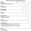
 STM32 Naming.png 3,726 × 2,291; 714 KB
 STM32 Overview.jpg 631 × 713; 137 KB
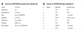
 STM32 Processors with Touch Sensors.png 803 × 160; 19 KB
 STM32 Programmer 5 boards bot view.jpg 3,341 × 1,222; 753 KB
 STM32 Programmer 5 boards top view.jpg 3,427 × 1,223; 846 KB
 STM32 Programmer bot view.jpg 1,587 × 896; 270 KB
 STM32 Programmer broken out.jpg 2,987 × 1,748; 979 KB
 STM32 Programmer broken out top view.jpg 1,547 × 783; 274 KB
 STM32 Programmer fully assembled - 5pcs.jpg 3,306 × 2,108; 1,020 KB
 STM32 Programmer rev. f Schematics.svg 1,052 × 744; 413 KB
 STM32 Programmer rev. f front and back.jpg 1,343 × 1,695; 411 KB
 STM32 Programmer rev. g Schematics.svg 1,052 × 744; 412 KB
 STM32 Programmer top view.jpg 1,652 × 903; 300 KB
 STM32 Read internal temperature and voltage reference - clock config.png 1,409 × 676; 47 KB
 ST Nucleo Overview.jpg 856 × 1,323; 606 KB
 Schematic with touch sensors.png 1,088 × 730; 19 KB
 Settings for LL.png 1,463 × 652; 27 KB
 Sipeed Longan Nano - btm view aligned.jpg 2,539 × 950; 389 KB
 Sipeed Longan Nano - btm view angled.jpg 2,890 × 1,142; 457 KB
 Sipeed Longan Nano - top view aligned.jpg 2,534 × 886; 386 KB
 Sipeed Longan Nano - top view angled.jpg 2,895 × 1,124; 509 KB
 SoloKey-A v. 1.2 schematics.png 1,039 × 851; 114 KB
 Stm32CubeMX Sys Settings.png 698 × 301; 13 KB
 Stm32CubeMx clock.png 1,557 × 686; 47 KB
 Stm32CubeMx crystal setting.png 692 × 409; 14 KB
 Stm32Dev SD-Card.jpg 2,304 × 3,501; 800 KB
 Stm32Dev Tight Buttons.jpg 1,275 × 815; 280 KB
 Stm32Dev rev. B - 5 pieces.jpg 3,502 × 1,216; 1 MB
 Stm32Dev rev. a schematic.svg 1,052 × 744; 440 KB
 Stm32Dev rev. b - top side unpopulated.jpg 1,866 × 1,109; 481 KB
 Stm32Dev rev. b - unpopulated.jpg 1,877 × 1,101; 379 KB
 Stm32dev rev. b.svg 1,052 × 744; 569 KB
 Stm32f103 series.png 993 × 608; 261 KB
 Success.png 553 × 270; 19 KB
- TM1637 Datasheet.pdf ; 688 KB
 TSC Pins.png 1,520 × 750; 123 KB
 Test.jpg 2,039 × 991; 369 KB
 Tim4 Global Interrupt.png 503 × 180; 9 KB
 Tim4 PWM Duty Cycle.png 468 × 398; 16 KB
 Tim4 PWM Pinout.png 673 × 485; 38 KB
 Tim4 PWM User Constants.png 464 × 216; 9 KB
 Tim4 configured for PWM on Channel 1.png 475 × 337; 7 KB
 Tim 4 Parameters.png 501 × 350; 15 KB
 Tim 4 User Variables.png 500 × 691; 18 KB
 Timer Encoder.png 483 × 321; 6 KB
 Timer clock.png 554 × 294; 10 KB
 Timer configuration.png 514 × 686; 22 KB
 Timer for statistics.png 452 × 468; 14 KB
 Top side view.png 1,554 × 946; 376 KB
 Top view.jpg 3,178 × 2,152; 838 KB
 Torex Semicon XC6206P332MR.png 363 × 364; 175 KB
 Touch Keyboard - bot.jpg 2,357 × 2,711; 380 KB
 Touch Keyboard - detail.jpg 2,089 × 764; 184 KB
 Touch Keyboard - top.jpg 2,643 × 3,104; 740 KB
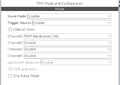
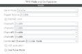
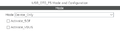
 Touch Mode and Configuration.png 724 × 714; 31 KB
 Touch PCB.jpg 1,037 × 855; 86 KB
 Touch PCB Layout.png 447 × 593; 27 KB
 Touch output.png 401 × 340; 23 KB
 Two Black Pill Boards.jpg 1,533 × 1,936; 528 KB
 Two Different Black Pill Boards.jpg 1,932 × 1,484; 510 KB
 Typical RAM layout.png 585 × 723; 88 KB
 USB-C Connector - hand soldered.jpg 1,203 × 857; 173 KB
 USB3300 Breakout.jpg 1,327 × 888; 263 KB
 USB3300 ULPI Breakout.jpg 891 × 829; 214 KB
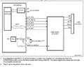
 USB Circuit w. 1.5 kOhm pull-up.png 848 × 670; 19 KB
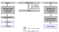 USB Debugging Architecture.png 927 × 500; 58 KB
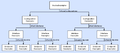 USB Descriptor Hierarchy.png 1,011 × 450; 43 KB
 USB Device Mode and Configuration.png 517 × 537; 17 KB
 USB HS Interface.png 689 × 549; 47 KB
 USB Mode.png 516 × 154; 2 KB
 User Constants.png 519 × 269; 10 KB
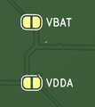 VBAT and VDDA solder jumpers.png 397 × 446; 16 KB
 VSCode Example - pinout.png 739 × 650; 116 KB
 VSCode Exmple Project Manager.png 1,274 × 853; 70 KB
 VSCode Open Folder.png 1,025 × 239; 15 KB
 Vscode debugging session.png 1,584 × 992; 175 KB
 Vscode make.png 365 × 587; 25 KB
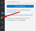 Vscode run and debug.png 347 × 301; 23 KB
 Vscode successful make.png 598 × 297; 37 KB
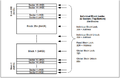
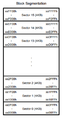 W25Q128 Block Segmentation.png 243 × 466; 21 KB
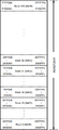 W25Q128 Blocks.png 331 × 721; 40 KB
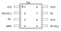 W25Q128 SOIC-8 Pinout.png 572 × 295; 16 KB
 W25Q128 mounted on black pill.png 808 × 442; 467 KB
 WCH-Link Bot.jpg 3,411 × 1,255; 389 KB
 WCH-Link Top.jpg 3,217 × 1,305; 571 KB
 WCH-Link in bag.jpg 4,333 × 2,493; 1.07 MB
 WS2812B Chain.png 938 × 178; 35 KB
 WS2812B Daisy Chain.png 301 × 474; 20 KB
 WS2812B Data Transmission Method.png 778 × 268; 49 KB
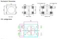 WS2812B Mechanical.png 688 × 452; 89 KB
 WS2812B Timing.png 874 × 152; 26 KB
 WS2812 bits.png 933 × 51; 5 KB
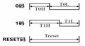 WS2812 sequence chart.png 301 × 162; 25 KB
 Winbond W25Q128 Layout.png 794 × 516; 65 KB
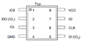 Winbond W25Q128 Pins.png 500 × 262; 14 KB
 Wireless.png 1,018 × 583; 208 KB


.jpg)


