STM32 internal temperature and voltage reference
Most, if not all, STM32 MCUs have a built-in temperature sensor (and a built-in voltage reference). While this temperature sensor needs calibration to achieve any kind of precision, it is usable to detect temperature changes.
Both the temperature sensor and the internal reference voltage are hooked up to the built-in ADC.
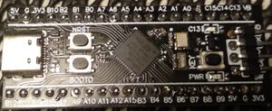
For this example, we are going to be using a so-called Black Pill board. The Black Pill board is using a STM32F411 and according to the datasheet that MCU has got one 12-bit ADC with up to 16 channels.
It would be entirely possible to simply read the value of the temperature ADC channel in the main loop of the application, but this would block the processor from doing anything else. A much more elegant way is to use a timer + DMA to make the measurements run entirely in hardware and then just read out the values as and when they are needed.
Notice, this article serves as an example. For simply measuring the internal temperature and printing out the values, the approach used here is way overkill. However, as an example it shows how to read sensor data.
Clock configuration
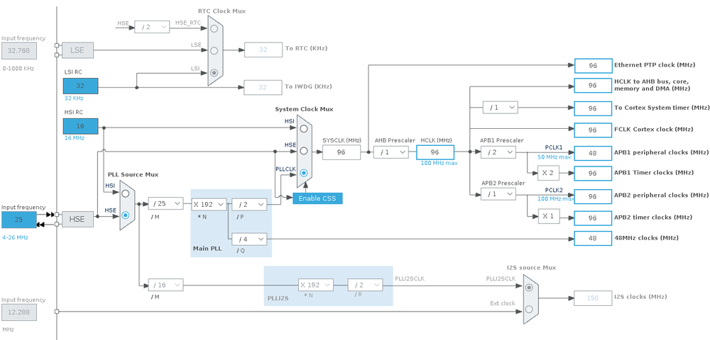
The Black Pill board have an on-board 25 MHz crystal. 25 MHz is a very silly value for a development board as it is complicated to derive a 48 MHz value from it (which is needed for USB). Thus, we configure the MCU to run at 96 MHz rather than the theoretical max of 100 MHz:
This gives us a timer clock (APB1 Timer Clocks and APB2 Timer Clocks) of 96 MHz.
Timer
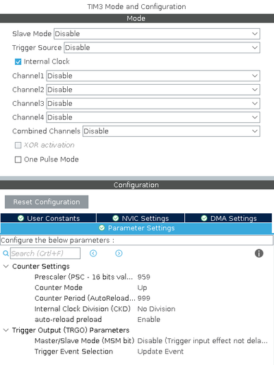
Our aim is to measure the temperature sensor and voltage reference 100 times each second. Since we configured the clock to run at 96 MHz we need to divide the clock by 960,000 to end up with 100 Hz.
This (combined with the clock configuration) will give us exactly 100 update events every second.
ADC
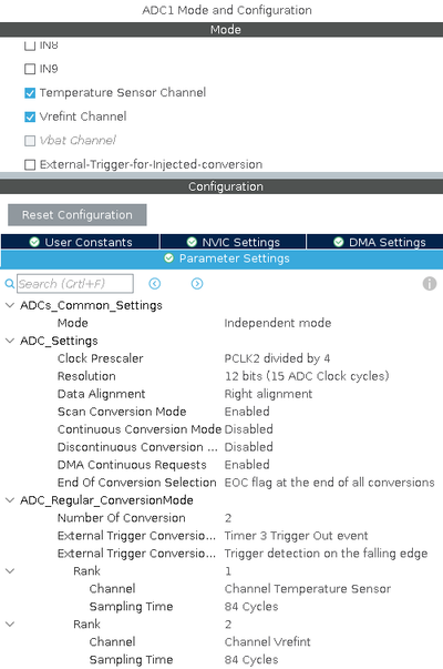
Next up is the configuration of the ADC itself. First the basic ADC settings:
The important values here is the "Scan Conversion Mode" and "DMA Continous Requests".
Also we configure the ADC sampling to be triggered by the timer that we previously configured.
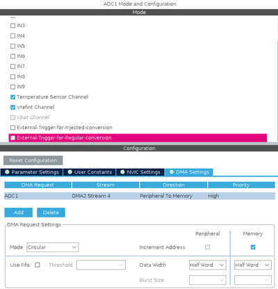
Since we want the ADC to use DMA, we also need to configure a DMA channel to capture the data:
Here we configure the DMA channel to use a circular buffer. In other words, each time a value is sampled, the memory address is increased for the next sample.
Calibration
The ADC measures analogue values as a fraction (4095) of VDDA. On the Black Pill board, VDDA is tied to the digital VDD. VDD is regulated by a cheap LDO and it can vary quite a bit (it's probably somewhat noisy as well). Fortunately, ST stores calibration data in the system memory and this calibration data can be used to establish the actual VDDA.
/* ADC internal channels related definitions */
/* Internal voltage reference VrefInt */
#define VREFINT_CAL_ADDR     ((uint16_t*) (0x1FFF7A2AU)) /* Internal voltage reference, address of parameter VREFINT_CAL:
                                                            VrefInt ADC raw data acquired at temperature 30 DegC
                                                            (tolerance: +-5 DegC), Vref+ = 3.3 V (tolerance: +-10 mV).
                                                         */
#define VREFINT_CAL_VREF     ( 3300UL)                   /* Analog voltage reference (Vref+) value with which temperature sensor
                                                            has been calibrated in production (tolerance: +-10 mV) (unit: mV).
                                                         */
/* Temperature sensor */
#define TEMPSENSOR_CAL1_ADDR ((uint16_t*) (0x1FFF7A2CU)) /* Internal temperature sensor, address of parameter TS_CAL1: On STM32F4,
                                                            temperature sensor ADC raw data acquired at temperature  30 DegC
                                                            (tolerance: +-5 DegC), Vref+ = 3.3 V (tolerance: +-10 mV).
                                                         */
#define TEMPSENSOR_CAL2_ADDR ((uint16_t*) (0x1FFF7A2EU)) /* Internal temperature sensor, address of parameter TS_CAL2: On STM32F4,
                                                            temperature sensor ADC raw data acquired at temperature 110 DegC
                                                            (tolerance: +-5 DegC), Vref+ = 3.3 V (tolerance: +-10 mV).
                                                         */
#define TEMPSENSOR_CAL1_TEMP (( int32_t)   30)           /* Internal temperature sensor, temperature at which temperature sensor
                                                            has been calibrated in production for data into TEMPSENSOR_CAL1_ADDR
                                                            (tolerance: +-5 DegC) (unit: DegC).
                                                         */
#define TEMPSENSOR_CAL2_TEMP (( int32_t)  110)           /* Internal temperature sensor, temperature at which temperature sensor
                                                            has been calibrated in production for data into TEMPSENSOR_CAL2_ADDR
                                                            (tolerance: +-5 DegC) (unit: DegC).
                                                         */
#define TEMPSENSOR_CAL_VREFANALOG ( 3300UL)              /* Analog voltage reference (Vref+) voltage with which temperature sensor
                                                            has been calibrated in production (+-10 mV) (unit: mV).
                                                         */
The formula is:
VDDA = VREFINT_CAL_VREF * *VREFINT_CAL_ADDR / vref / 1000
Where VREFINT_CAL_VREF is the voltage used at calibration (3300), VREFINT_CAL_ADDR contains an int16_t and vref is the measured value.
On a random Black Pill, the calibration data are like this:
VREFINT_CAL = 1507 (0x05e3)
TEMPSENSOR_CAL1 = 948 (0x03b4)
TEMPSENSOR_CAL2 = 1203 (0x04b3)
And we get the following raw data from the ADC:
VREF = 1560
TEMP = 998
Based on this, we can calculate the VDDA:
VDDA = 3300 * 1507 / 1560 / 1000 = 3.188
And based on that we can get the exact value of the internal voltage reference:
VREF = 3.188 / 4095 * 1560 / 1000 = 1.214
Both well within our expectations (3.3 V LDO supply and 1.21 V internal reference +/- 1 %).
Code
At this point, STM32CubeMX have done the bulk of the heavy lifting and the code becomes extremely simple.
First step is to create a buffer to store our sample data:
#define ADC_SAMPLES 10

uint16_t adc_buffer[ADC_SAMPLES * 2 * 2] = {0};
Here, we set the number of samples to 10. The actual buffer need to be big enough to hold the values of 2 ADC channels (the temperature and the voltage reference) and to be able to handle the circular buffer, we need to double the size. In other words, the actual size of the buffer will be 10 * 2 * 2 * 2 = 80 bytes.
In our "main" we need to start the timer and start the ADC DMA capture:
  /* USER CODE BEGIN 2 */

  HAL_TIM_Base_Start_IT(&htim3);

  HAL_ADC_Start_DMA(&hadc1, (uint32_t *)adc_buffer, ADC_SAMPLES * 2 * 2);

  /* USER CODE END 2 */
The STM32 HAL library will run a callback function twice for each buffer. We can use those callbacks to process the data:
/* Private user code ---------------------------------------------------------*/
/* USER CODE BEGIN 0 */

// Process half a buffer full of data
void process_adc_buffer(uint16_t *buffer) {

    uint32_t sum1 = 0, sum2 = 0;
    for (int i = 0; i < ADC_SAMPLES; ++i) {
    	sum1 += buffer[i * 2];
    	sum2 += buffer[1 + i * 2];
    }

    temp = (float)(sum1 * 0.322265625 / ADC_SAMPLES - 279);
    vref = (float)sum2 / 1000 / ADC_SAMPLES;

}


void HAL_ADC_ConvHalfCpltCallback(ADC_HandleTypeDef* hadc) {
	process_adc_buffer(&adc_buffer[0]);
}

void HAL_ADC_ConvCpltCallback(ADC_HandleTypeDef *hadc) {
	process_adc_buffer(&adc_buffer[ADC_SAMPLES * 2]);
}

/* USER CODE END 0 */
The STM32 HAL library will call the two functions HAL_ADC_ConvHalfCpltCallback and HAL_ADC_ConvCpltCallback when either the first half of the buffer is full or the second half. In our case we will handle the two halfs the same way, but use a different pointer depending.
The process_adc_buffer simply add the 10 samples together and calculate the value for temp and vref based on the average of the sampled values.
We can now print our our measurements in the main loop of the program:
  uint32_t now = 0, then = 0;

  for (;;)
  {

	  now = HAL_GetTick();
	  if (now % 1000 == 0 && now != then) {

		  printf("Temperature = %4.2f °C   Vref = %2.2f V\n", temp, vref);

		  then = now;
	  }

  }
The output (send to the USB virtual serial port) is:
Temperature = 32.50 °C   Vref = 1.50 V
Temperature = 32.44 °C   Vref = 1.50 V
Temperature = 32.37 °C   Vref = 1.50 V
Temperature = 32.47 °C   Vref = 1.50 V
Temperature = 32.63 °C   Vref = 1.50 V
Temperature = 32.44 °C   Vref = 1.50 V
Temperature = 32.41 °C   Vref = 1.50 V
Temperature = 32.50 °C   Vref = 1.50 V
Temperature = 32.50 °C   Vref = 1.50 V
Temperature = 32.63 °C   Vref = 1.50 V
Temperature = 32.66 °C   Vref = 1.50 V
Temperature = 32.57 °C   Vref = 1.50 V
Temperature = 32.44 °C   Vref = 1.50 V
Temperature = 32.53 °C   Vref = 1.50 V
Temperature = 32.57 °C   Vref = 1.50 V
Temperature = 32.47 °C   Vref = 1.50 V
Temperature = 32.44 °C   Vref = 1.50 V
Temperature = 32.50 °C   Vref = 1.50 V
Temperature = 32.63 °C   Vref = 1.50 V
Temperature = 32.53 °C   Vref = 1.50 V
Code on Github
This example is available on Github
