Difference between revisions of "STM32 internal temperature and voltage reference"
| Line 9: | Line 9: | ||
Notice, this article serves as an example. For simply measuring the internal temperature and printing out the values, the approach used here is way overkill. However, as an example it shows how to read sensor data. | Notice, this article serves as an example. For simply measuring the internal temperature and printing out the values, the approach used here is way overkill. However, as an example it shows how to read sensor data. | ||
| + | |||
| + | == Clock configuration == | ||
| + | |||
| + | The [[Black Pill]] board have an on-board 25 MHz crystal. 25 MHz is a very silly value for a development board as it is complicated to derive a 48 MHz value from it (which is needed for USB). Thus, we configure the MCU to run at 96 MHz rather than the theoretical max of 100 MHz: | ||
| + | |||
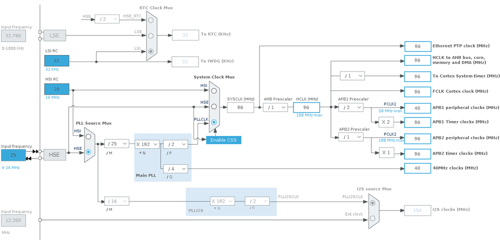
| + | [[File:STM32 Read internal temperature and voltage reference - clock config.png|1000px]] | ||
== Timer == | == Timer == | ||
Revision as of 05:08, 1 June 2021
Most - if not all - STM32 MCUs have a built-in temperature sensor (and a built-in voltage reference). While this temperature sensor needs calibration to achieve any kind of precision, it is usable to detect temperature changes.
Both the temperature sensor and the internal reference voltage are hooked up to the built-in ADC.
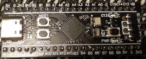
For this example, we are going to be using a so-called Black Pill board. The Black Pill board is using a STM32F411 and according to the datasheet that MCU has got one 12-bit ADC with up to 16 channels.
It would be entirely possible to simply read the value of the temperature ADC channel in the main loop of the application, but this would block the processor from doing anything else. A much more elegant way is to use a timer + DMA to make the measurements run entirely in hardware and then just read out the values as and when they are needed.
Notice, this article serves as an example. For simply measuring the internal temperature and printing out the values, the approach used here is way overkill. However, as an example it shows how to read sensor data.
Clock configuration
The Black Pill board have an on-board 25 MHz crystal. 25 MHz is a very silly value for a development board as it is complicated to derive a 48 MHz value from it (which is needed for USB). Thus, we configure the MCU to run at 96 MHz rather than the theoretical max of 100 MHz:
Timer
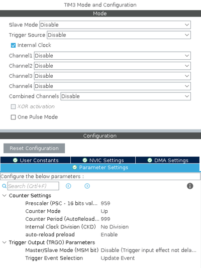
Our aim is to measure the temperature sensor and voltage reference 100 times each second. Thus our first step is to configure a timer to generate the necessary update events.


