Difference between revisions of "STM32 Timer PWM Input Capture"
(→Wiring) |
|||
| Line 20: | Line 20: | ||
== STM32CubeMX Setup == | == STM32CubeMX Setup == | ||
| − | + | We can now begin configuring the [[STM32]] in [[Stm32CubeMX]]. As usual the clock is critical. | |
[[File:PWM Input Capture example - clock settings.png|1000px]] | [[File:PWM Input Capture example - clock settings.png|1000px]] | ||
| + | |||
| + | The 25 MHz crystal oscillator on the [[Black Pill]] _can_ generate a 100 MHz clock, but even though USB is not needed in this example, the 48 MHz frequency needed for USB is not possible when the clock is set to 100 MHz. I therefore often use 96 MHz, as this can be used for USB as well. | ||
| + | |||
| + | The most important frequency is the APB1 timer clock. In this example that will be running at the full 96 MHz. | ||
| + | |||
| + | We will be using Timer 4 to generate the [[PWM]] signal. The setup of that timer looks like this: | ||
[[File:PWM Input Capture example - Timer 4 configuration.png|400px]] | [[File:PWM Input Capture example - Timer 4 configuration.png|400px]] | ||
| + | |||
| + | |||
[[File:PWM Input Capture example - Timer 2 confriguration.png|400px]] | [[File:PWM Input Capture example - Timer 2 confriguration.png|400px]] | ||
| − | + | == Code == | |
== Miscellaneous Links == | == Miscellaneous Links == | ||
* [https://github.com/lbthomsen/blackpill/tree/master/pwm_ic PWM Input Capture Example] for [[Black Pill]] | * [https://github.com/lbthomsen/blackpill/tree/master/pwm_ic PWM Input Capture Example] for [[Black Pill]] | ||
Revision as of 05:12, 13 March 2022
The timers in STM32 MCUs are incredible powerful. We have used them before to generate PWM Signals and to decode signals from rotary encoders. In this example we will use them to determine frequency an duty cycle of an external PWM signal.
For the example we will be using a Black Pill development board and we will be using the same MCU to both generate and to decode the PWM signal.
The source of the complete example is here.
Wiring
Since we are using the same board to generate and to decode the PWM signal, we need a jumper wire to connect the PWM Output to the PWM Input. The pinout resulting from the setup in the next section looks like this:
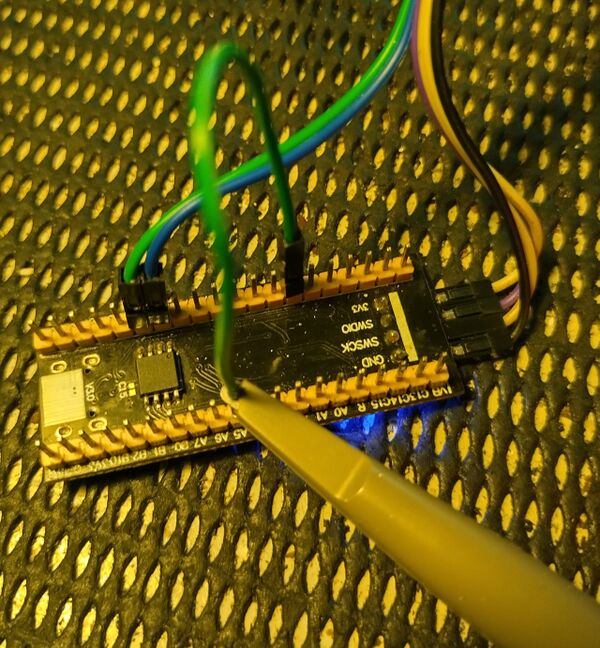
So, we will need to run a jumper wire from PB6 (the PWM output pin) to PA5 (the PWM input capture pin) - like this:
In this photo, a ST-Link device with serial port, and an oscilloscope probe has also been connected.
STM32CubeMX Setup
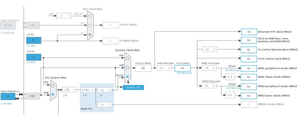
We can now begin configuring the STM32 in Stm32CubeMX. As usual the clock is critical.
The 25 MHz crystal oscillator on the Black Pill _can_ generate a 100 MHz clock, but even though USB is not needed in this example, the 48 MHz frequency needed for USB is not possible when the clock is set to 100 MHz. I therefore often use 96 MHz, as this can be used for USB as well.
The most important frequency is the APB1 timer clock. In this example that will be running at the full 96 MHz.
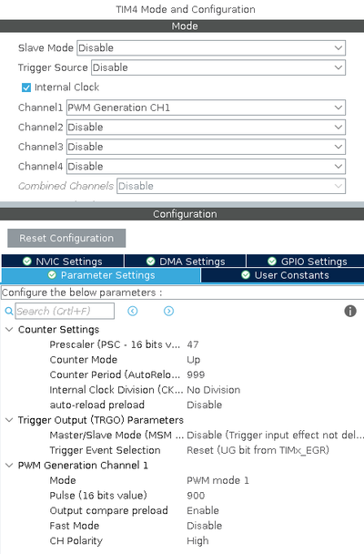
We will be using Timer 4 to generate the PWM signal. The setup of that timer looks like this:


