Difference between revisions of "STM32 Audio Analogue ADC and DAC using Timer + DMA"
imported>Lth |
imported>Lth |
||
| Line 25: | Line 25: | ||
[[File:ADCDAC Example User Constants.png|400px]] | [[File:ADCDAC Example User Constants.png|400px]] | ||
| + | |||
| + | Using these constant definitions, we can now configure the timer parameters: | ||
| + | |||
| + | [[File:ADCDAC Example Timer Parameters.png|400px]] | ||
Revision as of 10:09, 21 November 2020
This page deals with running the STM32 ADCs and DACs off of a timer at a sample rate adequate for Audio Data. We will be using a sample rate of 48000 Hz for both.
Configuring Clocks
For this we'll be using a stm32dev board which is equipped with a STM32F405RG processor and a 8 MHz external crystal.
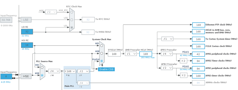
Using STM32CubeMx the clocks are configured like this:
As can be seen, the processor is using the external (HSE) crystal running at 8 MHz, to generate it's internal SYSCLK running at 168 MHz. From this clock the two timer clocks are derived, APB1 timer running at 84 MHz and APB2 timer at 168 MHz.
Configuring Timer for Audio Sampling
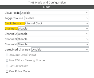
As mentioned earlier we are aiming for a sample rate of 48 kHz - which should be adequate for audible audio. To achieve this we'll configure Timer 8 to run at that frequency. First we'll be configuring the mode:
According to the datasheet, the STM32F405 Timer 8 is running off of APB2. We therefor need to divide the 168 MHz frequency of that down to our desired 48 kHz.
168 MHz / 48 kHz = 3500
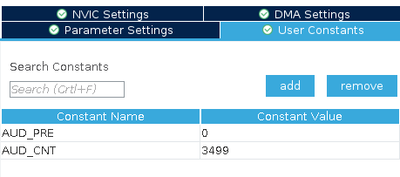
There are multiple ways to achieve that but a prescaler of 0 and a counter of 3499 should work. We define two user constants to this effect:
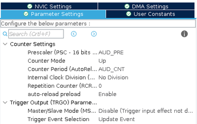
Using these constant definitions, we can now configure the timer parameters:


