Difference between revisions of "Black Pill"
(→Pinout) |
|||
| (11 intermediate revisions by the same user not shown) | |||
| Line 12: | Line 12: | ||
* 25 MHz main crystal | * 25 MHz main crystal | ||
* 32.768 kHz RTC crystal | * 32.768 kHz RTC crystal | ||
| + | * 512 kB Flash (STM32F411 version) | ||
| + | * 128 kB RAM | ||
| + | * 1 [[ADC]] (no [[DAC]]) | ||
* USB-C connector | * USB-C connector | ||
* Programming header | * Programming header | ||
| Line 17: | Line 20: | ||
== Pinout == | == Pinout == | ||
| − | [[File:black pill pinout.png| | + | <div class="res-img"> |
| + | [[File:black pill pinout.png|1400px]] | ||
| + | </div> | ||
| + | |||
| + | == Built-in LED == | ||
| + | |||
| + | Notice, the [[Black Pill]] board have got a built-in [[LED]] attached to PC13. This is perfectly Ok, if you want to toggle the [[LED]] on or off. Unfortunately, no timer channel is connected to this pin, so it is not normally possible to regulate the intensity using [[PWM]]. Fortunately, it '''is''' possible to do [[PWM]] by bit-banging the pin. See [[STM32 bit bang PWM]] for an explanation on how this can be done. | ||
| + | |||
| + | {{#ev:youtube|RNMuQwfvm74}} | ||
== Flash Layout == | == Flash Layout == | ||
| Line 52: | Line 63: | ||
* [https://stm32-base.org/assets/pdf/boards/original-schematic-STM32F401CCU6_WeAct_Black_Pill_V1.2.pdf Original Schematics vers. 1.2] | * [https://stm32-base.org/assets/pdf/boards/original-schematic-STM32F401CCU6_WeAct_Black_Pill_V1.2.pdf Original Schematics vers. 1.2] | ||
* [https://www.st.com/resource/en/datasheet/stm32f411ce.pdf STM32F411x Datasheet] | * [https://www.st.com/resource/en/datasheet/stm32f411ce.pdf STM32F411x Datasheet] | ||
| − | * [https://ipfs | + | * [https://ipfs.io/ipfs/QmUGduV94vdwiX5FpM5uAbNPBNw48gFXgJZyFJFeLJrbws/dm00119316-stm32f411xc-e-advanced-arm-based-32-bit-mcus-stmicroelectronics.pdf STM32F411xC/E advanced Arm®-based 32-bit MCUs Reference Manual] |
* [https://github.com/trebisky/stm32f411 Bare metal coding on the STM32F411/Black Pill] | * [https://github.com/trebisky/stm32f411 Bare metal coding on the STM32F411/Black Pill] | ||
| + | * [https://github.com/lbthomsen/blackpill/tree/master/bitbang_pwm Bit-bang PWM on built-in LED] | ||
Notice, most - if not all - clone boards match the 1.2 schematics. | Notice, most - if not all - clone boards match the 1.2 schematics. | ||
Latest revision as of 11:20, 9 May 2024
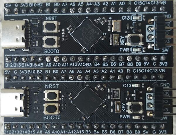
The Black Pill development board is a good choice. Of the commercially available development modules, this is one of the best. It was designed by WeAct Studio, but like the Blue Pill many different versions exist. Unlike the Blue Pill, at least at the time of writing this, they all appear to be using genuine STM32 processors (read: no cheaper clones exist). Here are two different ones, both of which I suspect are clones (and both working just fine):
Features
The Black Pills are typically based on a STM32F401 or STM32F411 (both of the above are the F411 version) and offers the following specs:
- STM32F4 (STM32F401 or STM32F411) processor
- Same footprint (I/O pins)
- 25 MHz main crystal
- 32.768 kHz RTC crystal
- 512 kB Flash (STM32F411 version)
- 128 kB RAM
- 1 ADC (no DAC)
- USB-C connector
- Programming header
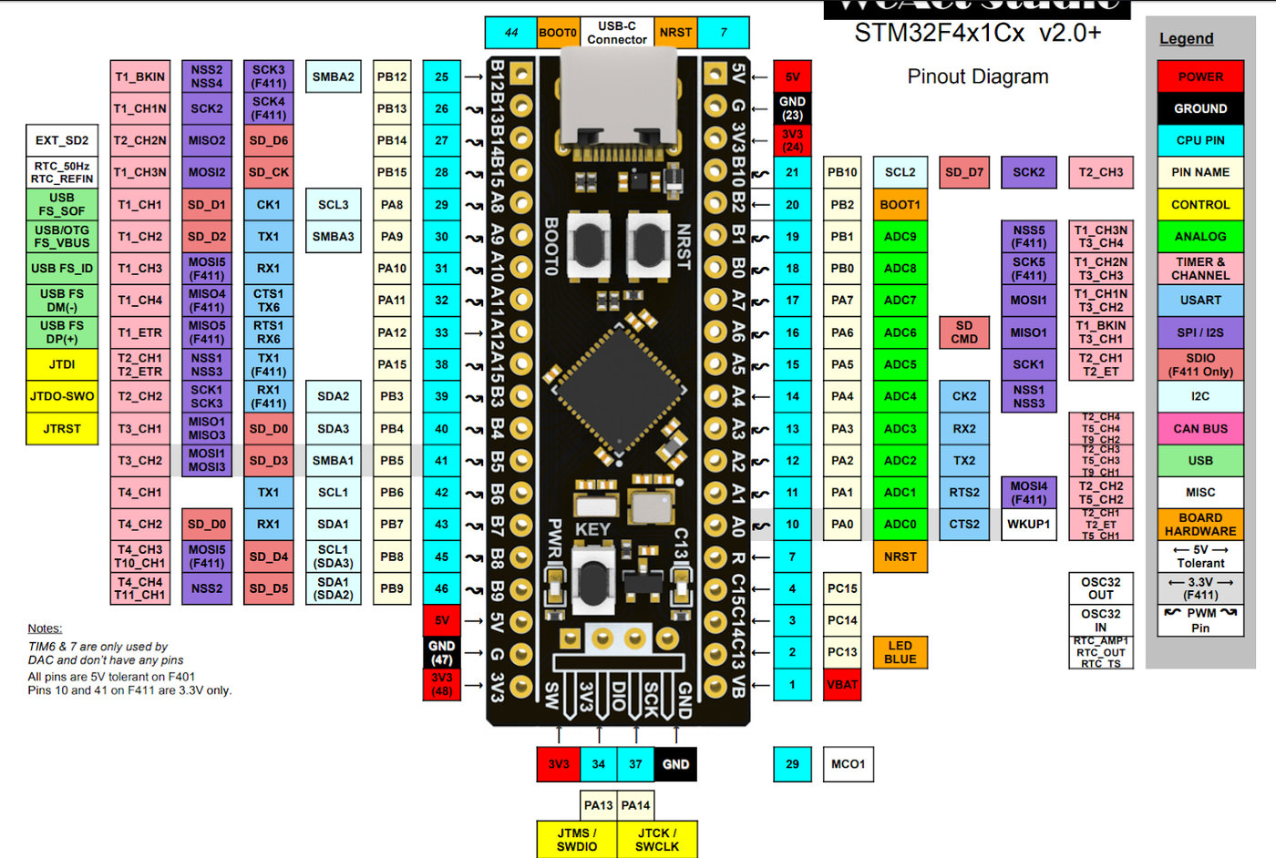
Pinout
Built-in LED
Notice, the Black Pill board have got a built-in LED attached to PC13. This is perfectly Ok, if you want to toggle the LED on or off. Unfortunately, no timer channel is connected to this pin, so it is not normally possible to regulate the intensity using PWM. Fortunately, it is possible to do PWM by bit-banging the pin. See STM32 bit bang PWM for an explanation on how this can be done.
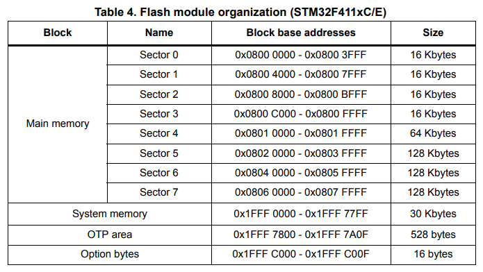
Flash Layout
EEPROM Footprint
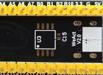
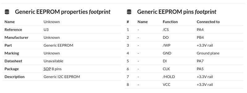
The Black Pill board usually have an unpopulated footprint on the reverse side of the PCB intended for a generic EEPROM:
On the Board Info page, this is documented as:
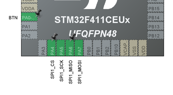
Unfortunately, the clone Black Pill boards are wired up different. The DO (MISO) is not wired up to PB4 as indicated but rather PA6 (which makes more sense anyway). Using STM32CubeMX, the right configuration is:
USB
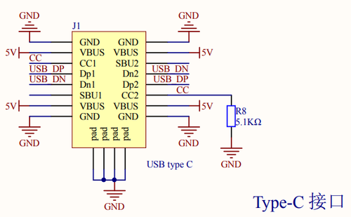
The STM32F411 MCU on the Black Pill boards can in principle run in USB Host mode. However, it is worth having a look at the schematics:
Both the CC lines are pulled to GND using a 5.1k resistor, which signals that this is a device, not a host. Also, there is no way to control the power delivery. In short, while the MCU on these boards can operate in USB Host mode, there is no way this can be reliably done on the Black Pill boards.
Miscellaneous Links
- WeAct Black Pill Github Repository
- Board Info
- Original Schematics ver. 2.0
- Original Schematics vers. 1.2
- STM32F411x Datasheet
- STM32F411xC/E advanced Arm®-based 32-bit MCUs Reference Manual
- Bare metal coding on the STM32F411/Black Pill
- Bit-bang PWM on built-in LED
Notice, most - if not all - clone boards match the 1.2 schematics.
