STM32 SD card with FatFs
In this article we will be interfacing a SD-card using STM32.
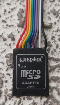
For this purpose we have modified a SD to Micro-SD adaptor by soldering 9 jumper leads on it (see photo on the right).
SD-Card Pinout
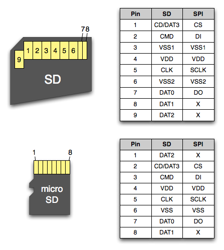
The pinout of a SD-card and a MicroSD-card are as follows:
It is important to notice that all SD-cards can be interfaced in two different ways:
DIY SD-card Adaptor
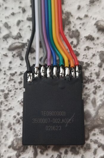
A quick way to hook up a SD-card to a STM32 is to use one of those SD to Micro-SD adaptors that come with most Micro-SD's when you buy them. I made one looking like this:
Combining that with the pinout from the previous section, we can make the following table:
| Pin | Color | SDIO | SPI |
|---|---|---|---|
| 1 | White | CD/Dat3 | CS |
| 2 | Grey | CMD | DI |
| 3 | Purple | VSS1 | VSS1 |
| 4 | Blue | VDD | VDD |
| 5 | Green | CLK | SCLK |
| 6 | Yellow | VSS2 | VSS2 |
| 7 | Orange | DAT0 | DO |
| 8 | Red | DAT1 | |
| 9 | Black | DAT2 |
As per the SD-card specification in both the case of SPI and SDIO, all signals except the clock should be pulled up. Our DIY adaptor does not include pull-up resistors, so we will have to rely on the internal ones, which are really quite weak but as long as the leads are not too long it should work ok.
SPI
NOTICE! While it is supported by most, some SD-cards do not support SPI access. If this fails for you, try with another card. Older cards are more likely to work.
SDIO
Some MCUs - for example the STM32F405 - includes a SDIO peripheral which can be used to drive a SD-card directly. Schematics will look like this:
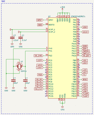
|
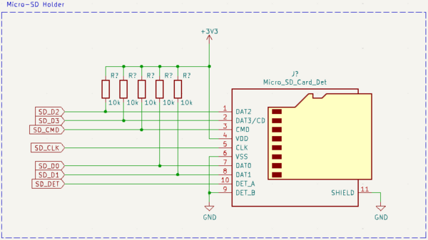
|
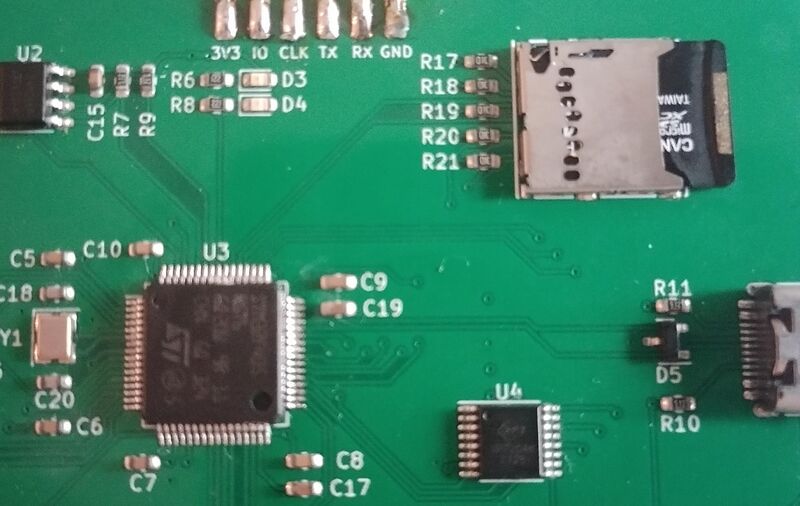
On a PCB that could look like this:
1-bit
4-bit
Gallery
The following quick "hack" was soldered together and it works flawlessly.
