STM32 SD card
In this article we will be interfacing a SD-card using STM32.
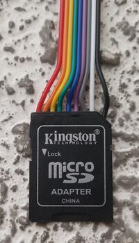
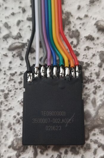
For this purpose we have modified a SD to Micro-SD adaptor by soldering 9 jumper leads on it.
SD-Card Pinout
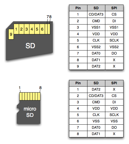
The pinout of a SD-card and a MicroSD-card are as follows:
It is important to notice that all SD-cards can be interfaced in two different ways:
DIY SD-card Adaptor
A quick way to hook up a SD-card to a STM32 is to use one of those SD to Micro-SD adaptors that come with most Micro-SD's when you buy them. I made one looking like this:
Combining that with the pinout from the previous section, we can make the following table:
| Pin | Color | SDIO | SPI |
|---|---|---|---|
| 1 | White | CD/Dat3 | CS |
| 2 | Grey | CMD | DI |
| 3 | Purple | VSS1 | VSS1 |
| 4 | Blue | VDD | VDD |
| 5 | Green | CLK | SCLK |
| 6 | Yellow | VSS2 | VSS2 |
| 7 | Orange | DAT0 | DO |
| 8 | Red | DAT1 | |
| 9 | Black | DAT2 |
As per the SD-card specification in both the case of SPI and SDIO, all signals except the clock should be pulled up. Our DIY adaptor does not include pull-up resistors, so we will have to rely on the internal ones, which are really quite weak.
SPI
SDIO
1-bit
4-bit
Gallery


