STM32 USB Device Renumeration
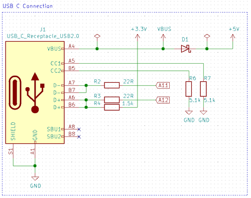
USB devices (aka. gadgets) need a 1.5 kOhm pull-up resistor on the D+ line in order for them to identify as devices (rather than hosts). On many STM32 MCUs this pull-up resistor is built-in (all MCUs with USB OTG). However, on the "device only" STM32's, like the STM32F103, this is not the case, so in modules using those processors one often see something like this in the schematics:
This generally works just fine with one noticeable exception - since the D+ line is permanently pulled high, the device will not re-enumerate when it is soft restarted (for example when flashing new firmware). This is of course a major PITA when doing USB related development.
ST themselves have dealt with this issue in their own ST-Link devices, which are based on the STM32F103. They've come up with this circuitry:
It is pretty obvious what they are doing there. As long as the RENUM pin is in high-impedance input mode or high, the transistor will be driven open and the 1.5 kOhm resistor will be connected to 3.3V.
While this is cool and will do the job, it does seem quite unnecessary to me. A much simpler solution is simply yanking the D+ line low before initializing USB.
Fortunately there is a rather elegant work-around. Before actually initialising the USB device, in "usb_device.c", add the following at the top of the MX_USB_DEVICE_Init function:
  /* USER CODE BEGIN USB_DEVICE_Init_PreTreatment */

    /*
     * Force host to re-enumerate device
     */
    GPIO_InitTypeDef GPIO_InitStruct = { 0 };              // All zeroed out
    GPIO_InitStruct.Pin = GPIO_PIN_12;                     // Hardcoding this - PA12 is D+
    GPIO_InitStruct.Mode = GPIO_MODE_OUTPUT_PP;            // Push-pull mode
    GPIO_InitStruct.Pull = GPIO_PULLDOWN;                  // Resetting so pull low
    GPIO_InitStruct.Speed = GPIO_SPEED_HIGH;               // Really shouldn't matter in this case
    HAL_GPIO_Init(GPIOA, &GPIO_InitStruct);                // Initialize with above settings
    HAL_GPIO_WritePin(GPIOA, GPIO_PIN_12, GPIO_PIN_RESET); // Yank low
    HAL_Delay(50);                                         // Enough time for host to disconnect device
    HAL_GPIO_WritePin(GPIOA, GPIO_PIN_12, GPIO_PIN_SET);   // Back high - so host will enumerate
    HAL_GPIO_DeInit(GPIOA, GPIO_PIN_12);                   // Deinitialize the pin

  /* USER CODE END USB_DEVICE_Init_PreTreatment */
What this does is essentially to configure the PA12 pin (USB D+) as a GPIO output pin and pull that to GND for 50 ms, before letting the USB initialisation continue as normal. The result is that the host notice the device has been disconnected and thus tries to re-enumerate immediately.
While being pulled low, the GPIO pin (D+) is going to sink 3.3V over a 1.5 kOhm resistor, so it will sink about 2.2 mA. That is well within spec and shouldn't cause any issues as it will only be pulled low for 50 ms.
After adding the above piece of code, the device will re-enumerate each time it is flashed (or otherwise restarted).

