STM32 W25Qxx
This page describes how to use W25Qxx Serial Flash/EEPROM chips with the STM32. The examples and code on this page has been developed on and for the Black Pill development board.
The resulting library can be found here: https://github.com/lbthomsen/stm32-w25qxx
An example using this library can be found here: https://github.com/lbthomsen/blackpill/tree/master/eeprom
Black Pill EEPROM
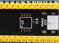
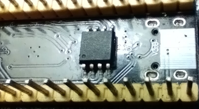
The Black Pill boards, whether original or copy, all includes an unpopulated footprint on the back side, with space for a "generic eeprom". This footprint can be populated with a wide range of compatible EEPROM chips.
The examples on this page are all using a Black Pill with a Winbond W25Q128.
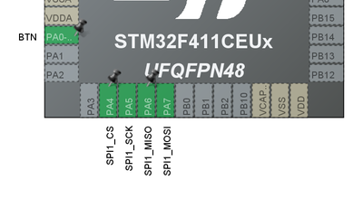
The original Black Pill board have been going through a few changes which can be a bit confusing. In all cases, the footprint is wired up to SPI1, but it is important to notice that on some boards the DO (MISO) pin of the W25Qxx is wired to PA6, and on some it is wired to PB4. Be certain to check which one is actually used.
In our case, the Black Pill board is clearly not an original, and PA6 is being used throughout:
W25Qxx Library
To make the W25Qxx easy to use, we need to develop a library with a set of simple functions:
W25QXX_result_t w25qxx_init(W25QXX_HandleTypeDef *w25qxx, SPI_HandleTypeDef *hspi, GPIO_TypeDef *cs_port, uint16_t cs_pin);
W25QXX_result_t w25qxx_read(W25QXX_HandleTypeDef *w25qxx, uint32_t address, uint8_t *buf, uint32_t len);
W25QXX_result_t w25qxx_write(W25QXX_HandleTypeDef *w25qxx, uint32_t address, uint8_t *buf, uint32_t len);
W25QXX_result_t w25qxx_erase(W25QXX_HandleTypeDef *w25qxx, uint32_t address, uint32_t len);
We will use a handle to keep information such as GPIO pins.
typedef struct {
	SPI_HandleTypeDef *spiHandle;
	GPIO_TypeDef *cs_port;
	uint16_t cs_pin;
	uint8_t manufacturer_id;
	uint16_t device_id;
	uint32_t block_size;
	uint32_t block_count;
	uint32_t sector_size;
	uint32_t sectors_in_block;
	uint32_t page_size;
	uint32_t pages_in_sector;
} W25QXX_HandleTypeDef;
init
The init function does a couple of things. It stores the SPI, and CS in the handler and attempt to retrieve a chip ID from the w25qxx device. Based on this chip ID, the memory layout of the device is stored.
W25QXX_result_t w25qxx_init(W25QXX_HandleTypeDef *w25qxx,
		SPI_HandleTypeDef *hspi, GPIO_TypeDef *cs_port, uint16_t cs_pin) {

	W25QXX_result_t result = W25QXX_Ok;

	DBG("w25qxx_init");

	w25qxx->spiHandle = hspi;
	w25qxx->cs_port = cs_port;
	w25qxx->cs_pin = cs_pin;

	uint32_t id = w25qxx_read_id(w25qxx);
	if (id) {
		w25qxx->manufacturer_id = (uint8_t) (id >> 16);
		w25qxx->device_id = (uint16_t) (id & 0xFFFF);

		switch (w25qxx->manufacturer_id) {
		case W25QXX_MANUFACTURER_WINBOND:

			w25qxx->block_size = 0x10000;
			w25qxx->sector_size = 0x1000;
			w25qxx->sectors_in_block = 0x0f;
			w25qxx->page_size = 0x100;
			w25qxx->pages_in_sector = 0x10;

			switch (w25qxx->device_id) {
			case 0x4018:
				w25qxx->block_count = 0x100;
				break;
			default:
				DBG("Unknown Winbond device")
				;
				result = W25QXX_Err;
			}

			break;
		default:
			DBG("Unknown manufacturer")
			;
			result = W25QXX_Err;
		}
	} else {
		result = W25QXX_Err;
	}

	if (result == W25QXX_Err) {
		// Zero the handle so it is clear initialization failed!
		memset(w25qxx, 0, sizeof(W25QXX_HandleTypeDef));
	}

	return result;

}
read
The read function first waits for the device to be ready (non-busy) and then read data:
W25QXX_result_t w25qxx_read(W25QXX_HandleTypeDef *w25qxx, uint32_t address, uint8_t *buf, uint32_t len) {

	DBG("w25qxx_read");

	// Transmit buffer holding command and address
	uint8_t tx[4] = {
	    W25QXX_READ_DATA,
		(uint8_t) (address >> 16),
		(uint8_t) (address >> 8),
		(uint8_t) (address),
	};

	// First wait for device to get ready
	if (w25qxx_wait_for_ready(w25qxx, HAL_MAX_DELAY) != W25QXX_Ok) {
		return W25QXX_Err;
	}

	cs_on(w25qxx);
	if (w25qxx_transmit(w25qxx, tx, 4) == W25QXX_Ok) { // size will always be fixed
		if (w25qxx_receive(w25qxx, buf, len) != W25QXX_Ok) {
			cs_off(w25qxx);
			return W25QXX_Err;
		}
	}
	cs_off(w25qxx);

	return W25QXX_Ok;
}
write
The write function, like the read function, waits for the device to be ready, and then clock out the data from the buffer provided:
W25QXX_result_t w25qxx_write(W25QXX_HandleTypeDef *w25qxx, uint32_t address,
		uint8_t *buf, uint32_t len) {

	DBG("w25qxx_write");

	// First wait for device to get ready
	if (w25qxx_wait_for_ready(w25qxx, HAL_MAX_DELAY) != W25QXX_Ok) {
		return W25QXX_Err;
	}

	if (w25qxx_write_enable(w25qxx) == W25QXX_Ok) {

		uint8_t tx[4] = {
			W25QXX_PAGE_PROGRAM,
			(uint8_t) (address >> 16),
			(uint8_t) (address >> 8),
			(uint8_t) (address),
		};

		cs_on(w25qxx);
		if (w25qxx_transmit(w25qxx, tx, 4) == W25QXX_Ok) { // size will always be fixed
			// Now write the buffer
			if (w25qxx_transmit(w25qxx, buf, len) != W25QXX_Ok) {
				cs_off(w25qxx);
				return W25QXX_Err;
			}
		}
		cs_off(w25qxx);

	}

	return W25QXX_Ok;
}
erase
The erase function is a little bit more complicated than the read/write functions, as it need to be aligned on sectors:
W25QXX_result_t w25qxx_erase(W25QXX_HandleTypeDef *w25qxx, uint32_t address,
		uint32_t len) {

	DBG("w25qxx_erase");

	W25QXX_result_t ret = W25QXX_Ok;

	// Let's determine the sector start
	uint32_t first_sector = address / w25qxx->sector_size;
	uint32_t last_sector = (address + len) / w25qxx->sector_size;

	DBG("w25qxx_erase: first sector: 0x%04X", first_sector);
	DBG("w25qxx_erase: last sector : 0x%04X", last_sector);

	for (uint32_t sector = first_sector; sector <= last_sector; ++sector) {

		DBG("Erasing sector %lu, starting at: 0x%08x", sector, sector * w25qxx->sector_size);

		// First we have to ensure the device is not busy
		if (w25qxx_wait_for_ready(w25qxx, HAL_MAX_DELAY) == W25QXX_Ok) {
			if (w25qxx_write_enable(w25qxx) == W25QXX_Ok) {

				uint32_t sector_start_address = sector * w25qxx->sector_size;

				uint8_t tx[4] = {
					W25QXX_SECTOR_ERASE,
					(uint8_t) (sector_start_address >> 16),
					(uint8_t) (sector_start_address >> 8),
					(uint8_t) (sector_start_address),
				};

				cs_on(w25qxx);
				if (w25qxx_transmit(w25qxx, tx, 4) != W25QXX_Ok) {
					ret = W25QXX_Err;
				}
				cs_off(w25qxx);
			}
		} else {
			ret = W25QXX_Timeout;
		}

	}

	return ret;
}
Using the library
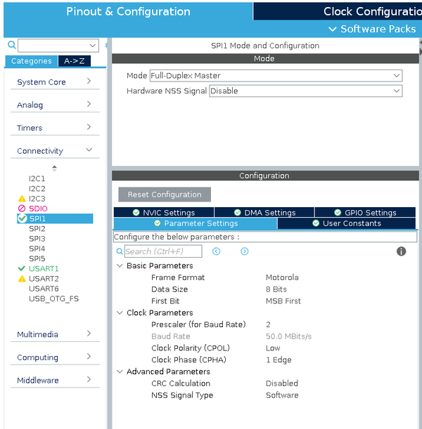
The STM32 must be configured with one SPI port and a CS (chip select). Notice the CS signal must be default HIGH and will be pulled low when SPI communication is active.
To use the library first we create a handler and a buffer:
W25QXX_HandleTypeDef w25qxx;
uint8_t buf[256] = {0}; // Buffer for playing with w25qxx
Initializing the library simply pass the handler to the init function with necessary SPI parameters:
  if (w25qxx_init(&w25qxx, &hspi1, SPI1_CS_GPIO_Port, SPI1_CS_Pin) == W25QXX_Ok) {
	  DBG("W25QXX successfully initialized");
	  DBG("Manufacturer       = 0x%2x", w25qxx.manufacturer_id);
	  DBG("Device             = 0x%4x", w25qxx.device_id);
	  DBG("Block size         = 0x%04x (%lu)", w25qxx.block_size, w25qxx.block_size);
	  DBG("Block count        = 0x%04x (%lu)", w25qxx.block_count, w25qxx.block_count);
	  DBG("Total size (in kB) = 0x%04x (%lu)", (w25qxx.block_count * w25qxx.block_size) / 1024, (w25qxx.block_count * w25qxx.block_size) / 1024);
  }
We can now read, write and erase:
		  DBG("Reading first page");
		  if (w25qxx_read(&w25qxx, 0, (uint8_t *)&buf, 256) == W25QXX_Ok) {
			  //DBG("  - sum = %lu", get_sum(buf, 256));
			  dump_hex("First page at start", 0, &buf, 256);
		  }

		  DBG("Erasing first page");
		  if (w25qxx_erase(&w25qxx, 0, 256) == W25QXX_Ok) {
			  DBG("Reading first page");
			  		  if (w25qxx_read(&w25qxx, 0, (uint8_t *)&buf, 256) == W25QXX_Ok) {
			  			  //DBG("  - sum = %lu", get_sum(buf, 256));
			  			dump_hex("After erase", 0, &buf, 256);
			  		  }
		  }

		  // Create a well known pattern
		  for (int i = 0; i < 256; ++i) buf[i] = i;
		  DBG("Writing first page");
		  if (w25qxx_write(&w25qxx, 0, (uint8_t *)&buf, 256) == W25QXX_Ok) {
			  DBG("Reading first page");
					  if (w25qxx_read(&w25qxx, 0, (uint8_t *)&buf, 256) == W25QXX_Ok) {
						  //DBG("  - sum = %lu", get_sum(buf, 256));
						  dump_hex("After write", 0, &buf, 256);
					  }
		  }
This will produce the following output:
Reading first page
w25qxx_read
First page at start
0x00000000: 00 01 02 03 04 05 06 07 08 09 0a 0b 0c 0d 0e 0f
0x00000010: 10 11 12 13 14 15 16 17 18 19 1a 1b 1c 1d 1e 1f
0x00000020: 20 21 22 23 24 25 26 27 28 29 2a 2b 2c 2d 2e 2f
0x00000030: 30 31 32 33 34 35 36 37 38 39 3a 3b 3c 3d 3e 3f
0x00000040: 40 41 42 43 44 45 46 47 48 49 4a 4b 4c 4d 4e 4f
0x00000050: 50 51 52 53 54 55 56 57 58 59 5a 5b 5c 5d 5e 5f
0x00000060: 60 61 62 63 64 65 66 67 68 69 6a 6b 6c 6d 6e 6f
0x00000070: 70 71 72 73 74 75 76 77 78 79 7a 7b 7c 7d 7e 7f
0x00000080: 80 81 82 83 84 85 86 87 88 89 8a 8b 8c 8d 8e 8f
0x00000090: 90 91 92 93 94 95 96 97 98 99 9a 9b 9c 9d 9e 9f
0x000000a0: a0 a1 a2 a3 a4 a5 a6 a7 a8 a9 aa ab ac ad ae af
0x000000b0: b0 b1 b2 b3 b4 b5 b6 b7 b8 b9 ba bb bc bd be bf
0x000000c0: c0 c1 c2 c3 c4 c5 c6 c7 c8 c9 ca cb cc cd ce cf
0x000000d0: d0 d1 d2 d3 d4 d5 d6 d7 d8 d9 da db dc dd de df
0x000000e0: e0 e1 e2 e3 e4 e5 e6 e7 e8 e9 ea eb ec ed ee ef
0x000000f0: f0 f1 f2 f3 f4 f5 f6 f7 f8 f9 fa fb fc fd fe ff
Erasing first page
w25qxx_erase
w25qxx_erase: first sector: 0x0000
w25qxx_erase: last sector : 0x0000
Erasing sector 0, starting at: 0x00000000
w25qxx_write_enable
Reading first page
w25qxx_read
After erase
0x00000000: ff ff ff ff ff ff ff ff ff ff ff ff ff ff ff ff
0x00000010: ff ff ff ff ff ff ff ff ff ff ff ff ff ff ff ff
0x00000020: ff ff ff ff ff ff ff ff ff ff ff ff ff ff ff ff
0x00000030: ff ff ff ff ff ff ff ff ff ff ff ff ff ff ff ff
0x00000040: ff ff ff ff ff ff ff ff ff ff ff ff ff ff ff ff
0x00000050: ff ff ff ff ff ff ff ff ff ff ff ff ff ff ff ff
0x00000060: ff ff ff ff ff ff ff ff ff ff ff ff ff ff ff ff
0x00000070: ff ff ff ff ff ff ff ff ff ff ff ff ff ff ff ff
0x00000080: ff ff ff ff ff ff ff ff ff ff ff ff ff ff ff ff
0x00000090: ff ff ff ff ff ff ff ff ff ff ff ff ff ff ff ff
0x000000a0: ff ff ff ff ff ff ff ff ff ff ff ff ff ff ff ff
0x000000b0: ff ff ff ff ff ff ff ff ff ff ff ff ff ff ff ff
0x000000c0: ff ff ff ff ff ff ff ff ff ff ff ff ff ff ff ff
0x000000d0: ff ff ff ff ff ff ff ff ff ff ff ff ff ff ff ff
0x000000e0: ff ff ff ff ff ff ff ff ff ff ff ff ff ff ff ff
0x000000f0: ff ff ff ff ff ff ff ff ff ff ff ff ff ff ff ff
Writing first page
w25qxx_write
w25qxx_write_enable
Reading first page
w25qxx_read
After write
0x00000000: 00 01 02 03 04 05 06 07 08 09 0a 0b 0c 0d 0e 0f
0x00000010: 10 11 12 13 14 15 16 17 18 19 1a 1b 1c 1d 1e 1f
0x00000020: 20 21 22 23 24 25 26 27 28 29 2a 2b 2c 2d 2e 2f
0x00000030: 30 31 32 33 34 35 36 37 38 39 3a 3b 3c 3d 3e 3f
0x00000040: 40 41 42 43 44 45 46 47 48 49 4a 4b 4c 4d 4e 4f
0x00000050: 50 51 52 53 54 55 56 57 58 59 5a 5b 5c 5d 5e 5f
0x00000060: 60 61 62 63 64 65 66 67 68 69 6a 6b 6c 6d 6e 6f
0x00000070: 70 71 72 73 74 75 76 77 78 79 7a 7b 7c 7d 7e 7f
0x00000080: 80 81 82 83 84 85 86 87 88 89 8a 8b 8c 8d 8e 8f
0x00000090: 90 91 92 93 94 95 96 97 98 99 9a 9b 9c 9d 9e 9f
0x000000a0: a0 a1 a2 a3 a4 a5 a6 a7 a8 a9 aa ab ac ad ae af
0x000000b0: b0 b1 b2 b3 b4 b5 b6 b7 b8 b9 ba bb bc bd be bf
0x000000c0: c0 c1 c2 c3 c4 c5 c6 c7 c8 c9 ca cb cc cd ce cf
0x000000d0: d0 d1 d2 d3 d4 d5 d6 d7 d8 d9 da db dc dd de df
0x000000e0: e0 e1 e2 e3 e4 e5 e6 e7 e8 e9 ea eb ec ed ee ef
0x000000f0: f0 f1 f2 f3 f4 f5 f6 f7 f8 f9 fa fb fc fd fe ff
The complete example for [Black Pill] can be found here.
Timing
Reading and writing the W25Qxx is relatively quick but erase is required before writing and erasing is quite slow. A quick stress test could look like this:
  // Let's do a stress test
  uint32_t start;
  uint32_t sectors = 0x1000; // Entire chip

  DBG("Erasing %lu sectors - 0x%08lx (%lu) bytes", sectors, sectors * w25qxx.sector_size, sectors * w25qxx.sector_size);
  start = HAL_GetTick();
  for (uint32_t i = 0; i < sectors; ++i) {
	  w25qxx_erase(&w25qxx, i * w25qxx.sector_size, sizeof(buf));
  }
  DBG("Done erasing - took %lu ms", HAL_GetTick() - start);

  fill_buffer(1, buf, sizeof(buf));

  DBG("Writing %lu sectors", sectors);
  start = HAL_GetTick();
  for (uint32_t i = 0; i < sectors; ++i) {
	  w25qxx_write(&w25qxx, i * w25qxx.sector_size, buf, sizeof(buf));
  }
  DBG("Done writing - took %lu ms", HAL_GetTick() - start);

  DBG("Reading %lu sectors", sectors);
  start = HAL_GetTick();
  for (uint32_t i = 0; i < sectors; ++i) {
	  w25qxx_read(&w25qxx, i * w25qxx.sector_size, buf, sizeof(buf));
  }
  DBG("Done reading - took %lu ms", HAL_GetTick() - start);
The "fill_buffer" function fills the 4 kB buffer with a sequence of 1, 2, 3...., 255, 1, 2.....
Running show the following output:
Erasing 4096 sectors - 0x01000000 (16777216) bytes
Done erasing - took 208030 ms
Writing 4096 sectors
Done writing - took 31433 ms
Reading 4096 sectors
Done reading - took 21717 ms
To be fair, in this particular case, we are erasing the chip 1 4 kB sector at the time. It is possible to erase by block (16 sectors) or the entire chip in one go and that is most likely much quicker. It is however not implemented in our library.


