Difference between revisions of "Boot0"
| Line 1: | Line 1: | ||
[[Category:STM32]][[Category:STM32 Hardware]]{{metadesc|STM32 Boot0 pin documentation and information}} | [[Category:STM32]][[Category:STM32 Hardware]]{{metadesc|STM32 Boot0 pin documentation and information}} | ||
| − | All [[STM32]] [[MCU]]s includes a [[GPIO]] pin labelled [[Boot0]]. This pin is used to select the [[STM32 Boot Modes|boot mode]] | + | All [[STM32]] [[MCU]]s includes a [[GPIO]] pin labelled [[Boot0]]. This pin is used to select the [[STM32 Boot Modes|boot mode]]. |
| + | |||
| + | See this page for how to jump to the System bootloader from an application: [[STM32 Jump to System Memory Bootloader]] | ||
== Hardware design == | == Hardware design == | ||
Revision as of 08:44, 18 October 2024
All STM32 MCUs includes a GPIO pin labelled Boot0. This pin is used to select the boot mode.
See this page for how to jump to the System bootloader from an application: STM32 Jump to System Memory Bootloader
Hardware design
It is extremely important to pull the Boot0 pin low during reset for normal operation.
If the pin is left unconnected in a hardware design it will "probably work", but it "might" on occasion detect a "high" on the pin and therefore decide to switch to the internal bootloader.
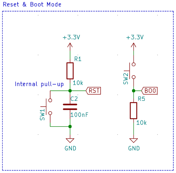
The proper way to deal with it can be seen on my Green Pill design:
The button SW2 is of course optional but while the pull-up resistor on the reset line (as indicated) is optional, the pull-down resistor R5 on Boot0 is not optional.
The strength of the pull-down is not very critical. Anything from 10k to 1M will do the job alright.
