Difference between revisions of "General-purpose input/output (GPIO)"
Jump to navigation
Jump to search
| Line 18: | Line 18: | ||
</div> | </div> | ||
| − | [[File:GPIO pin circuit.png| | + | Each of these ports control up to 16 individual [[GPIO]]s each controlled individually through 4 32-bit control registers. The electrical architecture of each [[GPIO]] looks like this: |
| + | |||
| + | <div class="res-img"> | ||
| + | [[File:GPIO pin circuit.png|800px]] | ||
| + | </div> | ||
Revision as of 02:35, 16 October 2024
A general-purpose input/output (GPIO) is an uncommitted digital signal pin on an integrated circuit or electronic circuit board which may be used as an input or output, or both, and is controllable by the user at runtime.
Internal Architecture
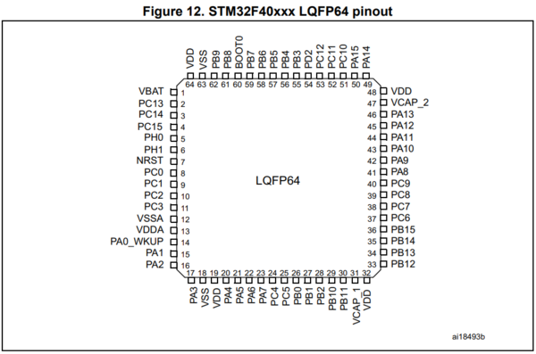
All STM32 MCUs have a high number of GPIOs. In fact, almost all pins on a MCU package, which is not dedicated a power pin are GPIOs:
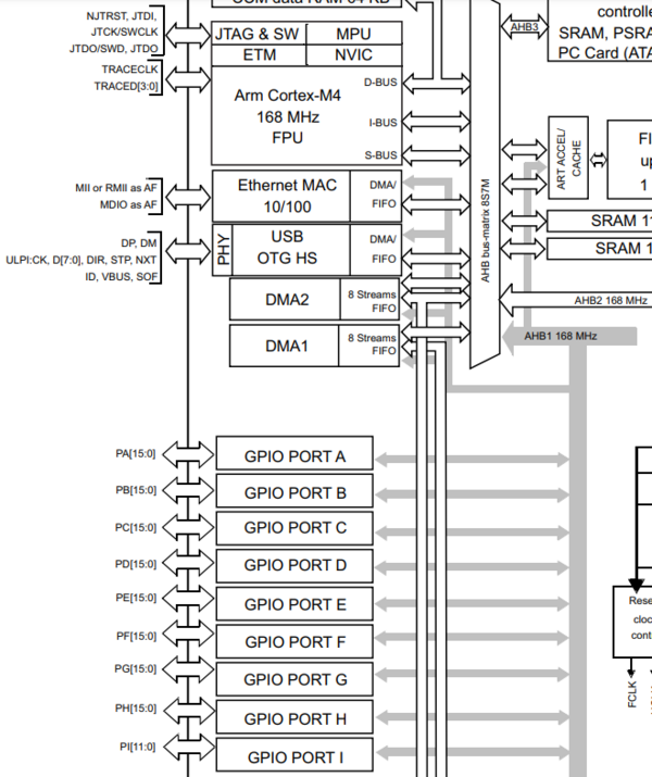
The GPIOs are divided into a number of ports (the actual number depends on the pins available on any particular package) labelled with letters and starting with "PortA".
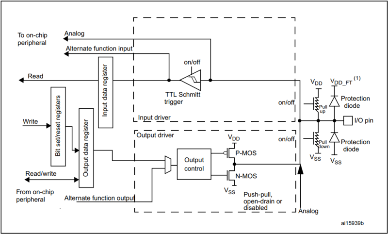
Each of these ports control up to 16 individual GPIOs each controlled individually through 4 32-bit control registers. The electrical architecture of each GPIO looks like this:


