Difference between revisions of "STM32 Rotary Encoder"
| Line 1: | Line 1: | ||
| − | [[Category:STM32]][[Category:STM32 Development]][[Category:STM32 HAL]]{{metadesc|How to handle rotary encoders using STM32 HAL}} | + | [[Category:STM32]][[Category:STM32 Development]][[Category:STM32 HAL]][[Category:C]]{{metadesc|How to handle rotary encoders using STM32 HAL}} |
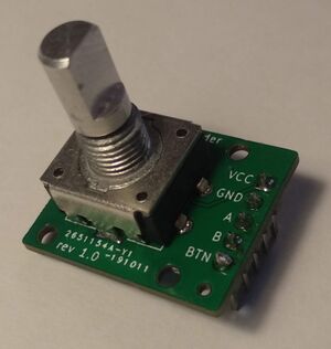
[[File:Rotary Encoder w. debounce circuitry.jpg|thumb|Rotary encoder on de-bouncing breakout board]] | [[File:Rotary Encoder w. debounce circuitry.jpg|thumb|Rotary encoder on de-bouncing breakout board]] | ||
Rotary Encoders are devices which will generate pulses when they are turned. | Rotary Encoders are devices which will generate pulses when they are turned. | ||
Revision as of 01:48, 7 September 2021
Rotary Encoders are devices which will generate pulses when they are turned.
Typically they will have two outputs with the pulses out of phase. By checking which pulse "comes first" the direction of the turn can be determined. It is not overly complicated to handle this manually, for example by hooking the signals up to an external GPIO Interrupt.
On this page, we will go through two different approaches:
Rotary encoder signals
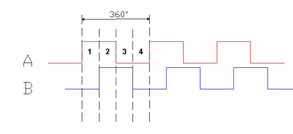
A rotary encoder will output 2 signals 90 degrees out of phase with each other.
By analysing the order of the transitions the steps can be counted and the direction can be detected.
Rotary encoder de-bouncing
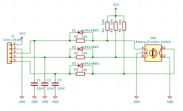
Rotary encoders are build with mechanical contacts and they are prone to "bouncing" (one press generate more than one interrupt". The "signals" can be cleaned up by implementing a low-pass filter like this:
I just happened to have a few of those rotary encoder breakout boards lying around.
Timer
STM32 Timers can be configured in encoder mode and do most of the "heavy lifting".
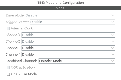
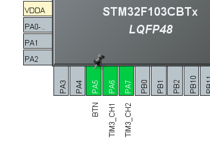
In STM32CubeMX a timer can be configured to combine two channels in Encoder mode.
This will highlight the necessary pins:
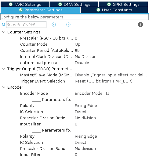
The various Parameter settings can then be adjusted:
The "Counter period" will determine the "range" of the counts. In this case, the counter period is set to 99, so the counter will count up to 99 and then wrap around to 0, and vice versa when rotating in the opposite direction.
Finally we can, if needed, enable an interrupt:
STM32CubeMX will now generate the bulk of the code needed.
We need to start the Timer:
HAL_TIM_Encoder_Start_IT(&htim3, TIM_CHANNEL_ALL);
We can now read out the encoder counter like this:
uint32_t last_print = 0, now = 0;

for (;;) {

	now = HAL_GetTick();
	if (now - last_print >= 1000) {
		DBG("Encoder counter = %lu", TIM3->CNT);
		last_print = now;
	}

}
Interrupt driven state machine
In order to handle the rotary decoder using interrupts let us look more closely at the signals.
As mentioned earlier, rotary encoders have two signals A and B which are phase offset. If we do a bit of binary match on these two bits:
S = B << 1 + A
We realise that there can be 4 different distinct phases: 0, 1, 2 and 3. When rotating in one direction the signals will look like this:
In other words, when rotating, the phase transitions will be 3 -> 2 -> 0 -> 1 -> 3
When rotating in the opposite direction this sequence will simply be reversed: 3 -> 1 -> 0 -> 2 -> 3
This now becomes really simple to deal with in the interrupt handler:
uint8_t rot_get_state() {
	return (uint8_t)((HAL_GPIO_ReadPin(ROT_B_GPIO_Port, ROT_B_Pin) << 1)
                | (HAL_GPIO_ReadPin(ROT_A_GPIO_Port, ROT_A_Pin)));
}

// External interrupts from rotary encoder
void HAL_GPIO_EXTI_Callback(uint16_t GPIO_Pin) {
	if (GPIO_Pin == ROT_A_Pin || GPIO_Pin == ROT_B_Pin) {

		rot_new_state = rot_get_state();

		DBG("%d:%d", rot_old_state, rot_new_state);

		// Check transition
		if (rot_old_state == 3 && rot_new_state == 2) {        // 3 -> 2 transition
			rot_cnt++;
		} else if (rot_old_state == 2 && rot_new_state == 0) { // 2 -> 0 transition
			rot_cnt++;
		} else if (rot_old_state == 0 && rot_new_state == 1) { // 0 -> 1 transition
			rot_cnt++;
		} else if (rot_old_state == 1 && rot_new_state == 3) { // 1 -> 3 transition
			rot_cnt++;
		} else if (rot_old_state == 3 && rot_new_state == 1) { // 3 -> 1 transition
			rot_cnt--;
		} else if (rot_old_state == 1 && rot_new_state == 0) { // 1 -> 0 transition
			rot_cnt--;
		} else if (rot_old_state == 0 && rot_new_state == 2) { // 0 -> 2 transition
			rot_cnt--;
		} else if (rot_old_state == 2 && rot_new_state == 3) { // 2 -> 3 transition
			rot_cnt--;
		}

		rot_old_state = rot_new_state;
	}
}
So what is the catch. On the surface this approach actually seems quite a lot simpler than using the timer. The issue is "bouncing". This approach works well with a rotary decoder which is properly electrically de-bounced, but it will fail miserably if the electrical transitions are "unclean" (multiple interrupts generated).
