Difference between revisions of "STM32 Rotary Encoder"
Jump to navigation
Jump to search
| Line 6: | Line 6: | ||
{{clear}} | {{clear}} | ||
| + | == Rotary encoder signals == | ||
| + | |||
| + | [[File:Rotary encoder signals.jpeg|600px]] | ||
| + | |||
== Rotary encoder de-bouncing == | == Rotary encoder de-bouncing == | ||
Revision as of 09:17, 26 July 2021
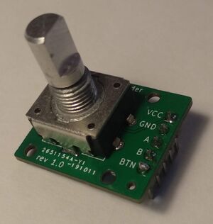
Rotary Encoders are devices which will generate pulses when they are turned.
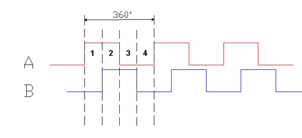
Typically they will have two outputs with the pulses out of phase. By checking which pulse "comes first" the direction of the turn can be determined. It is not overly complicated to handle this manually, for example by hooking the signals up to an external GPIO Interrupt.
Rotary encoder signals
Rotary encoder de-bouncing
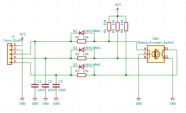
Rotary encoders are build with mechanical contacts and they are prone to "bouncing" (one press generate more than one interrupt". The "signals" can be cleaned up by implementing a low-pass filter like this:
I just happened to have a few of those rotary encoder breakout boards lying around.


