Difference between revisions of "STM32World"
| Line 68: | Line 68: | ||
| [[MEMW25Q128]] | | [[MEMW25Q128]] | ||
| Storage | | Storage | ||
| − | | [[W25Q128 | + | | [[W25Qxx|W25Q128]] SPI Serial Flash |
| Under development | | Under development | ||
|- | |- | ||
Revision as of 02:18, 5 May 2022
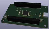
STM32World is a series of development boards designed for rapid development and prototyping.
The idea is to have MCU boards available with multiple MCU's (possibly including non ST ones such as the ones from GigaDevice).
The boards will be stackable but rather than trying to cram every single imaginable device into every board, these will be deliberately kept simple. A CAN transceiver board will include a CAN transceiver and nothing else.
As much as possible, peripheral board will be designed in such a way that they will not conflict with each other, even though this might not be possible to achieve 100 %.
All files for hardware and software is available at STM32World Github Repository
Form Factor
STM32World boards are meant to be stackable.
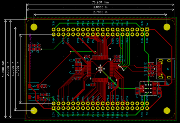
All boards are 3" x 2". In many cases this is much bigger than needed but PCB's are cheap and having the boards at that size makes layout much easier.
Board Ideas
| Name | Type | Description | Status | |
|---|---|---|---|---|
|
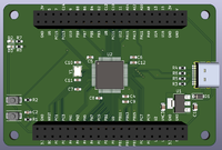
MCUSTM32F405 | MCU | MCU Board using the STM32F405 MCU | Under development |
|
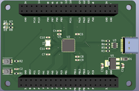
MCUSTM32F411 | MCU | MCU Board using the STM32F411 MCU | Under development |
|
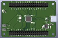
MCUSTM32F103 | MCU | MCU Board using the STM32F103 MCU | Under development |

|
MCUGD32F405 | MCU | MCU Board using the GD32F405 MCU | Under development |
|
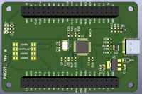
PRGSTL | Programmer | Board designed like a ST-Link/V2.1 device | Under development |
|
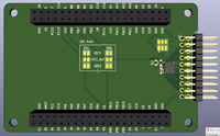
IOAW9523 | I/O | I²C AW9523 based GPIO Expander and LED driver | Under development |
|
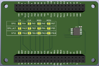
MEMW25Q128 | Storage | W25Q128 SPI Serial Flash | Under development |
| HID01 | Display/Keyboard | Display and touch keyboard | Under development | |
| DWS2812 | Display | WS2812B RGB LED Array | Under development |
Pin Use
The STM32 processors are not 100 % flexible in mapping I/O pins, so certain peripherals can only be mapped to certain pins. Because of that, some of our board will conflict with each other.
|
|
| Pin | MCUSTM32F405 | Remarks |
|---|---|---|
| PA0 | ||
| PA1 | ||
| PA2 | ||
| PA3 | ||
| PA4 | ||
| PA5 | ||
| PA6 | ||
| PA7 | ||
| PA8 | ||
| PA9 | ||
| PA10 | ||
| PA11 | D- | |
| PA12 | D+ | |
| PA13 | ||
| PA14 | ||
| PA15 | ||
| PB0 | ||
| PB1 | ||
| PB2 | ||
| PB3 | ||
| PB4 | ||
| PB5 | ||
| PB6 | ||
| PB7 | ||
| PB8 | ||
| PB9 | ||
| PB10 | ||
| PB11 | ||
| PB12 | ||
| PB13 | ||
| PB14 | ||
| PB15 | ||
| PC0 | ||
| PC1 | ||
| PC2 | ||
| PC3 | ||
| PC4 | ||
| PC5 | ||
| PC6 | ||
| PC7 | ||
| PC8 | ||
| PC9 | ||
| PC10 | ||
| PC11 | ||
| PC12 | ||
| PC13 | ||
| PC14 | ||
| PC15 |
