Difference between revisions of "Boot0"
Jump to navigation
Jump to search
| Line 1: | Line 1: | ||
| − | [[Category:STM32]][[Category:STM32 Hardware]]{{metadesc|STM32 Boot0 pin}} | + | [[Category:STM32]][[Category:STM32 Hardware]]{{metadesc|STM32 Boot0 pin documentation and information}} |
All [[STM32]] [[MCU]]s includes a [[GPIO]] pin labelled [[Boot0]]. This pin is used to select the [[STM32 Boot Modes|boot mode]] | All [[STM32]] [[MCU]]s includes a [[GPIO]] pin labelled [[Boot0]]. This pin is used to select the [[STM32 Boot Modes|boot mode]] | ||
Revision as of 01:42, 6 August 2022
All STM32 MCUs includes a GPIO pin labelled Boot0. This pin is used to select the boot mode
Hardware design
It is extremely important to pull the Boot0 pin low during reset for normal operation.
If the pin is left unconnected in a hardware design it will "probably work", but it "might" on occasion detect a "high" on the pin and therefore decide to switch to the internal bootloader.
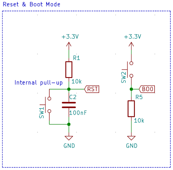
The proper way to deal with it can be seen on my Green Pill design:
The button SW2 is of course optional but while the pull-up resistor on the reset line (as indicated) is optional, the pull-down resistor R5 on Boot0 is not optional.
The strength of the pull-down is not very critical. Anything from 10k to 1M will do the job alright.
