Difference between revisions of "I²C"
| (2 intermediate revisions by the same user not shown) | |||
| Line 4: | Line 4: | ||
== The {{I2C}} Bus == | == The {{I2C}} Bus == | ||
| − | The {{I2C}} bus consists of two data signals, one clock and one bi-directional data line. One master and multiple slaves can be connected in parallel to the same bus. The signal pins of all devices are so-called open-drain, meaning they will never supply a voltage to the signal line but either be shorted to GND or in high-impedance mode. For that reason, both clock and data will need to be pulled high by a resistor. The benefit of this approach is that if multiple slaves respond simultaneously they never risk frying each other. The size of the pull-up resistor depends on the application. On a very short bus (5-10 cm tops) with only one mater and one slave, the resistor can be quite big (read: internal pull-up in a | + | The {{I2C}} bus consists of two data signals, one clock and one bi-directional data line. One master and multiple slaves can be connected in parallel to the same bus. The signal pins of all devices are so-called open-drain, meaning they will never supply a voltage to the signal line but either be shorted to GND or in high-impedance mode. For that reason, both clock and data will need to be pulled high by a resistor. The benefit of this approach is that if multiple slaves respond simultaneously they never risk frying each other. The size of the pull-up resistor depends on the application. On a very short bus (5-10 cm tops) with only one mater and one slave, the resistor can be quite big (read: internal pull-up in a [[STM32]] [[MCU]] will do just fine). This is known as a weak pull-up. On a longer bus or a bus with more devices, a stronger pull-up is needed, meaning a smaller resistor. 4.7K to 10K is common. |
| + | |||
| + | [[File:I2C-Interface.png|600px]] | ||
== {{I2C}} Addresses == | == {{I2C}} Addresses == | ||
| + | |||
| + | Since multiple slaves can be attached to any given {{I2C}} bus, it is necessary to address which device is targeted. The master does this by first transmitting a 7-bit (10 bit is possible) address which uniquely identifies the target. | ||
{| class="wikitable" | {| class="wikitable" | ||
| Line 55: | Line 59: | ||
|} | |} | ||
| − | + | Notice the address itself is 7 bits but it is shifted left one bit and the least significant bit - bit 0 - indicates whether a read or a write follows. | |
| − | |||
Latest revision as of 05:54, 7 October 2024
I²C stands for Inter-Integrated Circuit and is pronounced I-squared-C or I-to-C. It is a synchronious multi-master, multi-slave serial communication bus invented in 1982 by Philips Semiconductors.
The I²C Bus
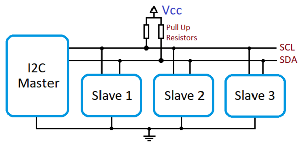
The I²C bus consists of two data signals, one clock and one bi-directional data line. One master and multiple slaves can be connected in parallel to the same bus. The signal pins of all devices are so-called open-drain, meaning they will never supply a voltage to the signal line but either be shorted to GND or in high-impedance mode. For that reason, both clock and data will need to be pulled high by a resistor. The benefit of this approach is that if multiple slaves respond simultaneously they never risk frying each other. The size of the pull-up resistor depends on the application. On a very short bus (5-10 cm tops) with only one mater and one slave, the resistor can be quite big (read: internal pull-up in a STM32 MCU will do just fine). This is known as a weak pull-up. On a longer bus or a bus with more devices, a stronger pull-up is needed, meaning a smaller resistor. 4.7K to 10K is common.
I²C Addresses
Since multiple slaves can be attached to any given I²C bus, it is necessary to address which device is targeted. The master does this by first transmitting a 7-bit (10 bit is possible) address which uniquely identifies the target.
| Field: | S | I2C address field | R/W' | A | I2C message sequences... | P | ||||||
|---|---|---|---|---|---|---|---|---|---|---|---|---|
| Type | Start | Byte 1 | ACK | Byte X, etc.
Rest of the read or write message goes here |
Stop | |||||||
| Bit position in byte X | 7 | 6 | 5 | 4 | 3 | 2 | 1 | 0 | ||||
| 7-bit address pos | 7 | 6 | 5 | 4 | 3 | 2 | 1 | |||||
| Note | MSB | LSB | 1 = Read | |||||||||
| 0 = Write | ||||||||||||
Notice the address itself is 7 bits but it is shifted left one bit and the least significant bit - bit 0 - indicates whether a read or a write follows.
