Difference between revisions of "DFRobot 10 DOF"
Jump to navigation
Jump to search
| (8 intermediate revisions by the same user not shown) | |||
| Line 1: | Line 1: | ||
| − | [[Category:STM32]][[Category:STM32 Development]][[Category:Components and Modules]][[Category:STM32CubeMX]][[Category:STM32CubeIde]][[Category:I²C]]{{metadesc|How to use a 10 DOF MEMS IMU sensor module with STM32}}[[File:DFRobot 10 DOF v1.0.jpg|thumb| | + | [[Category:STM32]][[Category:STM32 Development]][[Category:Components and Modules]][[Category:STM32CubeMX]][[Category:STM32CubeIde]][[Category:I²C]]{{metadesc|How to use a 10 DOF MEMS IMU sensor module with STM32}}[[File:DFRobot 10 DOF v1.0.jpg|thumb|400px]] |
The DFRobot 10 DOF sensor module contains 4 different [[I²C]] sensors: | The DFRobot 10 DOF sensor module contains 4 different [[I²C]] sensors: | ||
| Line 8: | Line 8: | ||
Each of these sensors will be handled on a separate page but a general overview follows on this page. | Each of these sensors will be handled on a separate page but a general overview follows on this page. | ||
| + | |||
| + | == Schematics == | ||
| + | |||
| + | DFRobot provides schematics for most of their product. The schematic for the 10 DOF board is this: | ||
| + | |||
| + | <div class="res-img"> | ||
| + | [[File:10_DOF_Schematic.png]] | ||
| + | </div> | ||
| + | |||
| + | As can be seen, all four sensors are wired up to the same {{I2C}} bus. It's a pity the individual interrupt lines are not wired out to the header as that would have made the board a LOT more usable. | ||
== {{I2C}} bus == | == {{I2C}} bus == | ||
| + | |||
| + | The four sensors show up on the {{I2C}} bus like this: | ||
<pre> | <pre> | ||
| Line 38: | Line 50: | ||
|- | |- | ||
| 0x77 | | 0x77 | ||
| − | | BMP085 | + | | [[#BMP085 Pressure/Temperature Sensor|BMP085 Pressure/Temperature Sensor]] |
|} | |} | ||
== Adxl345 Accelerometer == | == Adxl345 Accelerometer == | ||
| − | == ITG3200 Gyro == | + | == ITG3200 Gyro == |
| + | |||
| + | === ITG3200 Documentation === | ||
| + | |||
| + | * [https://product.tdk.com/system/files/dam/doc/product/sensor/mortion-inertial/gyro/data_sheet/itg-3200-datasheet.pdf ITG3200 Product Specification] | ||
| + | * [https://invensense.tdk.com/wp-content/uploads/2015/02/ITG-3200-Register-Map.pdf ITG3200 Register Map & Register Descriptions] | ||
== HMC5883L Compass == | == HMC5883L Compass == | ||
Latest revision as of 05:18, 3 October 2024
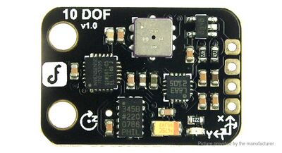
The DFRobot 10 DOF sensor module contains 4 different I²C sensors:
- Adxl345 accelerometer
- ITG3200 gyro
- HMC5883L Compass
- BMP085 pressure sensor
Each of these sensors will be handled on a separate page but a general overview follows on this page.
Schematics
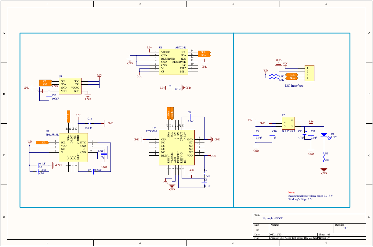
DFRobot provides schematics for most of their product. The schematic for the 10 DOF board is this:
As can be seen, all four sensors are wired up to the same I²C bus. It's a pity the individual interrupt lines are not wired out to the header as that would have made the board a LOT more usable.
I²C bus
The four sensors show up on the I²C bus like this:
Scan i2c2
-- -- -- -- -- -- -- -- -- -- -- -- -- -- -- --
-- -- -- -- -- -- -- -- -- -- -- -- -- -- 1e --
-- -- -- -- -- -- -- -- -- -- -- -- -- -- -- --
-- -- -- -- -- -- -- -- -- -- -- -- -- -- -- --
-- -- -- -- -- -- -- -- -- -- -- -- -- -- -- --
-- -- -- 53 -- -- -- -- -- -- -- -- -- -- -- --
-- -- -- -- -- -- -- -- 68 -- -- -- -- -- -- --
-- -- -- -- -- -- -- 77 -- -- -- -- -- -- -- --
| ID | Device |
|---|---|
| 0x1e | HMC5883L Compass |
| 0x53 | ADXL345 Accelerometer |
| 0x68 | ITG3200 Gyro |
| 0x77 | BMP085 Pressure/Temperature Sensor |

