Difference between revisions of "4 LEDs Hooked up to GPIO"
Jump to navigation
Jump to search
(Created page with "Category:Components and ModulesCategory:ElectronicsCategory:Work in progress{{metadesc|4 LEDs Hooked up to GPIO}} For one of the STM32 Getting Started Tutorial V...") |
|||
| Line 4: | Line 4: | ||
I quickly soldered together the following circuit: | I quickly soldered together the following circuit: | ||
| − | [[File:4 LEDs.png| | + | <div class="res-img"> |
| + | [[File:4 LEDs.png|600px]] | ||
| + | </div> | ||
| + | |||
| + | Soldered with a resistor in-line and heat-shrink tubing it ended up like this: | ||
| + | |||
| + | [[File:4 LEDs 1.jpg|600px]] | ||
| + | |||
| + | [[File:4 LEDs 2.jpg|600px]] | ||
Latest revision as of 08:36, 25 August 2024
For one of the Youtube Videos I needed to hook up multiple LEDs to multiple GPIO's.
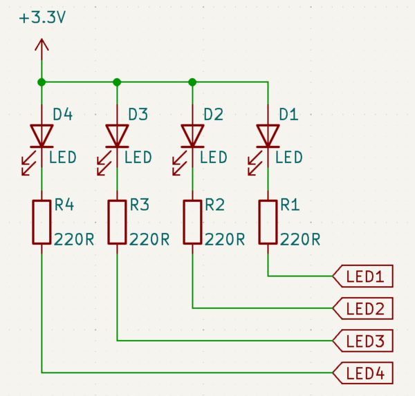
I quickly soldered together the following circuit:
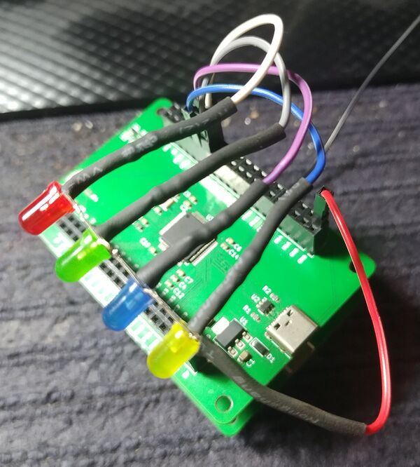
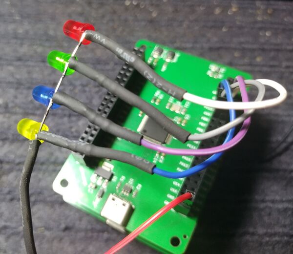
Soldered with a resistor in-line and heat-shrink tubing it ended up like this:


