Difference between revisions of "ColorLight I5"
Jump to navigation
Jump to search
| (8 intermediate revisions by the same user not shown) | |||
| Line 1: | Line 1: | ||
| − | [[Category:FPGA]] | + | [[Category:FPGA]][[Category:Work in progress]] |
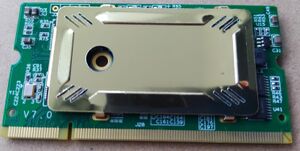
[[File:ColorLight I5 top.jpg|300px|thumb|ColorLight I5 module]] | [[File:ColorLight I5 top.jpg|300px|thumb|ColorLight I5 module]] | ||
== ColorLight I5 Module == | == ColorLight I5 Module == | ||
| Line 20: | Line 20: | ||
<img src="https://tomverbeure.github.io/assets/colorlight_i5/colorlight_i5_ext_board_pin_mapping.svg"/> | <img src="https://tomverbeure.github.io/assets/colorlight_i5/colorlight_i5_ext_board_pin_mapping.svg"/> | ||
</div> | </div> | ||
| + | |||
| + | == Button and LED Board == | ||
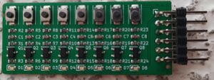
| + | [[File:IO Button and LED - top view.jpg|300px|thumb]] | ||
| + | The [[#Extension Board|Extension Board]] has got a number of I/O's neatly arranged together in groups of 8, each group with it's own 3.3V power and GND. To be able to add input buttons and output LED's, I created a small I/O board for this purpose. | ||
| + | |||
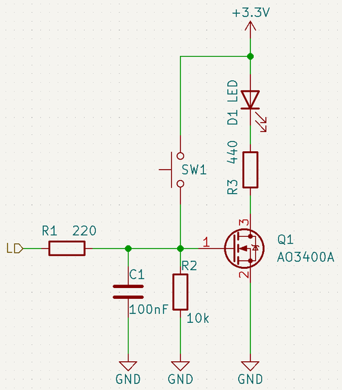
| + | [[File:IO Button LED schematics.png|500px]] | ||
| + | |||
| + | In order not to put a load on the I/O pin, the LEDs are driven by a MOSFET. | ||
| + | |||
| + | When a I/O port is running as an input (need a pull down) the LED will light up when the button is pressed. | ||
== Gallery == | == Gallery == | ||
| Line 29: | Line 39: | ||
File:ColorLight I5 bot.jpg | File:ColorLight I5 bot.jpg | ||
</gallery> | </gallery> | ||
| − | |||
== Miscellaneous Links == | == Miscellaneous Links == | ||
| Line 37: | Line 46: | ||
* [https://github.com/danderson/ulxs/blob/main/lpf.md Documentation of lpf files] | * [https://github.com/danderson/ulxs/blob/main/lpf.md Documentation of lpf files] | ||
* [https://stm32world.com/images/9/9f/LFE5U-25F-8BG381C.pdf ECP5 and ECP5-5G Family Datasheet] | * [https://stm32world.com/images/9/9f/LFE5U-25F-8BG381C.pdf ECP5 and ECP5-5G Family Datasheet] | ||
| − | * [ | + | * [https://stm32world.com/images/2/29/FPGA-TN-02032-1-3-ECP5-ECP5G-sysIO-Usage-Guide.pdf ECP5 and ECP5-5G sys I/O Usage Guide] |
Latest revision as of 02:08, 25 November 2022
ColorLight I5 Module
The ColorLight I5 module is designed and sold to drive LED displays. As such they make a lot of them and get the FPGA cheaper than they are commonly available.
Features
- ECP5 LFE5U-25F FPGA
- 24000 LUTs
- 56 sysMEM block RAMs of 16kb each
Extension Board
Extension Board Pinout
Courtesy of Tom Verbeure's excellent post:
Button and LED Board
The Extension Board has got a number of I/O's neatly arranged together in groups of 8, each group with it's own 3.3V power and GND. To be able to add input buttons and output LED's, I created a small I/O board for this purpose.
In order not to put a load on the I/O pin, the LEDs are driven by a MOSFET.
When a I/O port is running as an input (need a pull down) the LED will light up when the button is pressed.


