Difference between revisions of "Demiurge 1"
| (28 intermediate revisions by the same user not shown) | |||
| Line 1: | Line 1: | ||
| − | [[Category:Awesome Audio Apparatus]]{{metadesc|Demiurge Eurorack | + | [[Category:Awesome Audio Apparatus]][[Category:Demiurge]]{{metadesc|Demiurge Eurorack Module overview}} |
The idea about the Demiurge emerged back in 2019 and the first prototype was developed around the [[ESP32]] [[MCU]]. During initial testing of this prototype we concluded that the SDK of the ESP32 was not mature enough to handle the real time audio stuff. Because of that, the design was modified to use a [[STM32F405]] MCU. Unfortunately, around the time we were ready to start selling these, the [[STM32F405]] disappeared from the market completely. | The idea about the Demiurge emerged back in 2019 and the first prototype was developed around the [[ESP32]] [[MCU]]. During initial testing of this prototype we concluded that the SDK of the ESP32 was not mature enough to handle the real time audio stuff. Because of that, the design was modified to use a [[STM32F405]] MCU. Unfortunately, around the time we were ready to start selling these, the [[STM32F405]] disappeared from the market completely. | ||
== Hardware == | == Hardware == | ||
| + | In 2022, prototyping restarted as supply of [[RISC-V]] [[MCU]] [[CH32V307]] became available, which has very similar peripherals and is nearly pin compatible with [[STM32F405]]. The PCB layout is made so that with relatively minor manual changes, it is possible to mount [[STM32F405]], [[STM32F407]] and [[STM32F730]]. Some time in the future, we are likely to stock some/all of these variants in our store. | ||
| − | === Schematics | + | * Two analog outputs, 12-bits, -10V to +10V, DC coupled to be equally suitable for audio, CV and Gate functionality. |
| + | * Four analog inputs, 12-bits, -10V to +10V, and also DC coupled for the same reasons. | ||
| + | * One digital input/output for Gate or Trig functionality, 0-5V range. | ||
| + | * Four Potentiometers | ||
| + | * Four RGB LEDs accessible from I2C driver chip AW20036 with current limiting and PWM. | ||
| + | * Four push buttons connected directly to GPIOs (PB10, PB2, PB1, PB0) | ||
| + | * Power over 16-pin standard Eurorack power header, LDO for 3.3V to avoid switching noise. | ||
| + | * Programming header, with SWDIO/SWCLK (flashing) and USART (debugging tty) | ||
| + | * Optional SDcard connector | ||
| + | * Optional USB-C connector (very difficult to solder) | ||
| + | |||
| + | == Software == | ||
| + | * [[Demiurge Sound Processing Engine]] | ||
| + | |||
| + | == Schematics == | ||
<div class="res-img"> | <div class="res-img"> | ||
| − | [[File:Demiurge 1 rev f.svg| | + | [[File:Demiurge 1 rev f.svg|1500px]] |
</div> | </div> | ||
| − | + | ||
| + | == Photos Rev E == | ||
| + | |||
<div> | <div> | ||
| − | [[File:demiurge1-RevE-1.png| | + | [[File:demiurge1-RevE-1.png|150px]] |
| − | [[File:demiurge1-RevE-2.jpg| | + | [[File:demiurge1-RevE-2.jpg|180px]] |
| − | [[File:demiurge1-RevE-3.jpg| | + | [[File:demiurge1-RevE-3.jpg|200px]] |
| + | [[File:demiurge1-RevF-4.jpg|350px]] | ||
| + | [[File:demiurge1-RevF-8.jpg|350px]] | ||
</div> | </div> | ||
| − | == | + | == Photos Rev F == |
| − | + | ||
| − | + | <div> | |
| + | [[File:demiurge1-RevF-14.jpg|270px]] | ||
| + | [[File:demiurge1-RevF-13.jpg|200px]] | ||
| + | [[File:demiurge1-RevF-12.jpg|200px]] | ||
| + | [[File:demiurge1-RevF-11.jpg|200px]] | ||
| + | [[File:demiurge1-RevF-10.jpg|200px]] | ||
| + | [[File:demiurge1-RevF-3.jpg|180px]] | ||
| + | </div> | ||
== Miscellaneous Links == | == Miscellaneous Links == | ||
Latest revision as of 09:23, 9 November 2022
The idea about the Demiurge emerged back in 2019 and the first prototype was developed around the ESP32 MCU. During initial testing of this prototype we concluded that the SDK of the ESP32 was not mature enough to handle the real time audio stuff. Because of that, the design was modified to use a STM32F405 MCU. Unfortunately, around the time we were ready to start selling these, the STM32F405 disappeared from the market completely.
Hardware
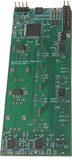
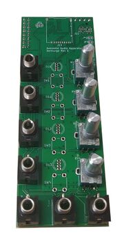
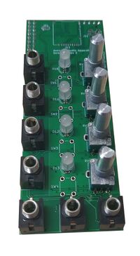
In 2022, prototyping restarted as supply of RISC-V MCU CH32V307 became available, which has very similar peripherals and is nearly pin compatible with STM32F405. The PCB layout is made so that with relatively minor manual changes, it is possible to mount STM32F405, STM32F407 and STM32F730. Some time in the future, we are likely to stock some/all of these variants in our store.
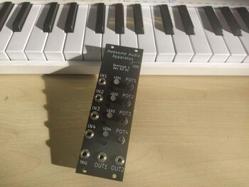
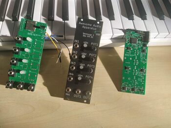
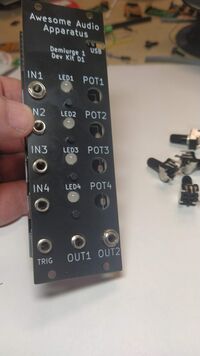
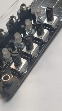
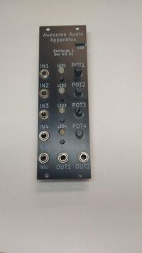
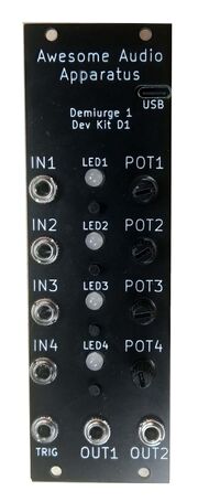
- Two analog outputs, 12-bits, -10V to +10V, DC coupled to be equally suitable for audio, CV and Gate functionality.
- Four analog inputs, 12-bits, -10V to +10V, and also DC coupled for the same reasons.
- One digital input/output for Gate or Trig functionality, 0-5V range.
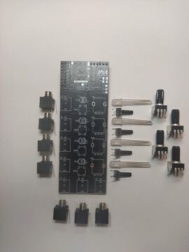
- Four Potentiometers
- Four RGB LEDs accessible from I2C driver chip AW20036 with current limiting and PWM.
- Four push buttons connected directly to GPIOs (PB10, PB2, PB1, PB0)
- Power over 16-pin standard Eurorack power header, LDO for 3.3V to avoid switching noise.
- Programming header, with SWDIO/SWCLK (flashing) and USART (debugging tty)
- Optional SDcard connector
- Optional USB-C connector (very difficult to solder)

