Difference between revisions of "STM32 SD"
Jump to navigation
Jump to search
| (One intermediate revision by the same user not shown) | |||
| Line 9: | Line 9: | ||
! F411 | ! F411 | ||
! F405 | ! F405 | ||
| − | ! Color | + | ! Color |
! Description | ! Description | ||
|- | |- | ||
| DAT3 | | DAT3 | ||
| 1 | | 1 | ||
| − | | | + | | PB5 |
| | | | ||
| + | | White | ||
| Serial Data 3 | | Serial Data 3 | ||
|- | |- | ||
| Line 22: | Line 23: | ||
| PA6 | | PA6 | ||
| | | | ||
| + | | Orange | ||
| Command | | Command | ||
|- | |- | ||
| Line 28: | Line 30: | ||
| N/C | | N/C | ||
| | | | ||
| + | | | ||
| Not connected/used on micro-SD | | Not connected/used on micro-SD | ||
|- | |- | ||
| Line 34: | Line 37: | ||
| 3.3V | | 3.3V | ||
| | | | ||
| + | | Red | ||
| Power supply | | Power supply | ||
|- | |- | ||
| Line 40: | Line 44: | ||
| PB15 | | PB15 | ||
| | | | ||
| + | | Yellow | ||
| Clock | | Clock | ||
|- | |- | ||
| Line 46: | Line 51: | ||
| GND | | GND | ||
| | | | ||
| + | | Black | ||
| Ground | | Ground | ||
|- | |- | ||
| Line 52: | Line 58: | ||
| PB4 | | PB4 | ||
| | | | ||
| + | | Green | ||
| Serial Data 0 | | Serial Data 0 | ||
|- | |- | ||
| Line 58: | Line 65: | ||
| PA8 | | PA8 | ||
| | | | ||
| + | | Blue | ||
| Serial Data 1 | | Serial Data 1 | ||
|- | |- | ||
| Line 64: | Line 72: | ||
| PA9 | | PA9 | ||
| | | | ||
| + | | Brown | ||
| Serial Data 2 | | Serial Data 2 | ||
|} | |} | ||
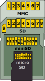
| align=right | [[File:MMC-SD-miniSD-microSD-Color-Numbers-Names.png|150px]] | | align=right | [[File:MMC-SD-miniSD-microSD-Color-Numbers-Names.png|150px]] | ||
|} | |} | ||
