Difference between revisions of "STM32 WS2812 (NeoPixel RGB LED)"
| Line 13: | Line 13: | ||
{{#ev:youtube|0T7BsdSnXhY}} | {{#ev:youtube|0T7BsdSnXhY}} | ||
| − | |||
| − | |||
| − | |||
| − | |||
== Protocol Analysis == | == Protocol Analysis == | ||
Revision as of 04:35, 19 December 2024
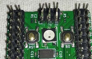
When developing the STM32Dev board a WS2812B RGB LED was including connected to the PC6 GPIO.
The WS2812B LED contains 3 LEDS: red, green and blue and each of these LEDS can be set at 256 different brightness levels. These levels are controlled with a bit stream running at 800 kHz and multiple LEDS (up to 1000-ish) can be chained after each other.
Searching the Internet there are a lot of suggestions and implementations dealing with the ws2812 LEDs, so obviously I decided to take a different approach. This approach is described on this page.
Example
Before digging into the details, here's an example of a STM32F411 Black Pill driving an 8 x 8 matrix of WS2812 LEDs:
Protocol Analysis
WS2812 LEDs are daisy chained together like this:
When sending data each LED need 24 bit - 8 bit for each color. The first LED in the chain will "use" the first 24 bit and then pass any following bit to the next LED in the chain and so forth. After a reset (a pause with no data) this cycle repeats.
For each individual LED the 24 bits are expected like this:
Notice that for the WS2812B the order is GRB (Green, Red, Blue).
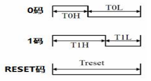
Each bit is send as one pulse. The difference between high and low time indicates if the bit is set or reset:
The bits are send at a frequency of 800 kHz (800000 bits per second) so each bit in total takes 1.25 μs. The early WS2812s were really timing critical but the later models are a lot less critical. Official timing for the WS2812B is:
Implementation
There are a number of ways, driving a string of WS2812's could potentially be implemented on STM32 MCU's. It is most certainly possible to bit-bang the protocol using a couple of timers. Running with a 800 kHz bit-stream, it is however quite expensive in terms of resources (MCU cycles) and the timing is extremely critical, so we will be looking at alternative methods. A better approach would be to use one of the existing peripherals in the STM32 MCU to handle both the timing and the bitstream. Fortunately, at least two such peripherals exist.
SPI
One of the better approaches I have seen involve using the MOSI signal of SPI to drive the LEDs (while ignoring the SCK). During transmit, the SPI peripheral will toggle the MOSI followed by a clock indicating the data is valid. By ignoring the clock and just using the MOSI, the bitstream necessary could be achieved. Imagine sending 11100000 vs. 00000111.
Properly implemented this approach could possibly benefit from the use of DMA.
PWM
An alternative approach, and the approach we will be following, is to use one of the many timer PWM channels included in the STM32. At first glance this approach might appear a bit complicated, as the duty cycles will need to change for each pulse. This is however possible by combining the PWM with a DMA buffer.
Library on Github
The library is available on Github:
https://github.com/lbthomsen/stm32-ws2812


