Difference between revisions of "STM32 SD card"
Jump to navigation
Jump to search
| Line 23: | Line 23: | ||
| White | | White | ||
| CD/Dat3 | | CD/Dat3 | ||
| + | | CS | ||
| + | |- | ||
| + | | 2 | ||
| + | | Grey | ||
| + | | CMD | ||
| DI | | DI | ||
| + | |- | ||
| + | | 3 | ||
| + | | Purple | ||
| + | | VSS1 | ||
| + | | VSS1 | ||
| + | |- | ||
| + | | 4 | ||
| + | | Blue | ||
| + | | VDD | ||
| + | | VDD | ||
| + | |- | ||
| + | | 5 | ||
| + | | Green | ||
| + | | CLK | ||
| + | | SCLK | ||
| + | |- | ||
| + | | 6 | ||
| + | | Yellow | ||
| + | | VSS2 | ||
| + | | VSS2 | ||
| + | |- | ||
| + | | 7 | ||
| + | | Orange | ||
| + | | DAT0 | ||
| + | | DO | ||
| + | |- | ||
| + | | 8 | ||
| + | | Red | ||
| + | | DAT1 | ||
| + | | | ||
| + | |- | ||
| + | | 9 | ||
| + | | Black | ||
| + | | DAT2 | ||
| + | | | ||
| + | | | ||
|} | |} | ||
Revision as of 03:55, 22 November 2024
In this article we will be interfacing a SD-card using STM32.
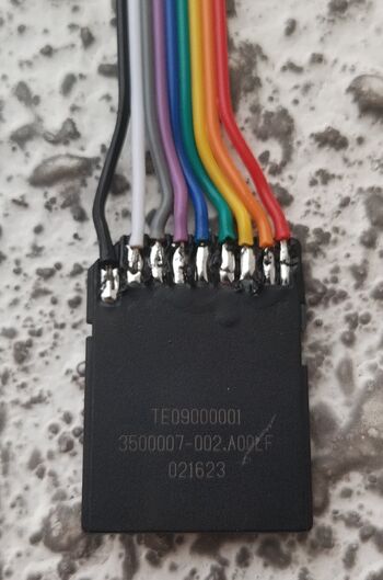
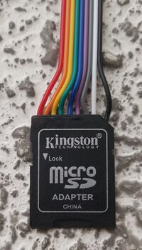
DIY SD-card Adaptor
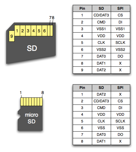
SD-Card Pinout

|

|
| Pin | Color | SDIO | SPI | |
|---|---|---|---|---|
| 1 | White | CD/Dat3 | CS | |
| 2 | Grey | CMD | DI | |
| 3 | Purple | VSS1 | VSS1 | |
| 4 | Blue | VDD | VDD | |
| 5 | Green | CLK | SCLK | |
| 6 | Yellow | VSS2 | VSS2 | |
| 7 | Orange | DAT0 | DO | |
| 8 | Red | DAT1 | ||
| 9 | Black | DAT2 |
SPI
SDIO
1-bit
4-bit
Gallery


