Difference between revisions of "STM32 bit bang PWM"
m (Lth moved page STM32 Bit bang PWM to STM32 bit bang PWM) |
|||
| Line 60: | Line 60: | ||
} | } | ||
</pre> | </pre> | ||
| + | |||
| + | === Using BSRR === | ||
| + | |||
| + | After implementing the bit banging using bit-banding, I came to realize that this could also be implemented simply by using the BSRR register: | ||
| + | |||
| + | <pre> | ||
| + | void HAL_TIM_PeriodElapsedCallback(TIM_HandleTypeDef *htim) { | ||
| + | |||
| + | if (htim->Instance == LED_PWM_TIM) { | ||
| + | ++led_pwm_cnt; // The counter is 8 bit so will wrap around after 255 | ||
| + | |||
| + | // Use BSRR to set or reset bit 13 of the LED GPIO port | ||
| + | LED_GPIO_Port->BSRR = led_pwm_cnt >= led_pwm_val ? GPIO_BSRR_BS13 : GPIO_BSRR_BR13; | ||
| + | } | ||
| + | |||
| + | } | ||
| + | </pre> | ||
| + | |||
| + | The GPIO_BSRR_BS13 and GPIO_BSRR_BR13 macros, contain a formula which calculates the values, but as these are most likely optimized by the compiler into constants, this is likely to perform just as well as the bit-banding approach. | ||
== Result == | == Result == | ||
Revision as of 03:50, 10 May 2024
On many of the cheaper STM32 Development Boards there is a LED attached to PC13. This is perfectly ok if you want to switch it on or off, but PC13 is not attached to any of the timer channels, so it will not be possible to control the brightness using PWM.
Fortunately, while not ideal, it is possible to bitbang the PWM in a manner which doesn't require too much computation. Contrary to PWM using a Timer channel, it does require some computation in the MCU.
Bit-banding
Bit-banding is a feature of all STM32 MCUs. Because STM32 are 32-bit MCUs they got a huge address space, much bigger than what is needed to address available memory. Each byte of memory has got a dedicated address for each bit, so if a single bit needs to be set or reset, a value of 0 or 1 can be written to that address. Without digging into details, the following macro will calculate the necessary address.
#define BITBAND_BIT_ADDR(src_byte_addr, bit) (((((uint32_t)(src_byte_addr) & 0x000fffff) << 5) | ((uint32_t)(src_byte_addr) & 0xfff00000) | 0x02000000) + (((uint32_t)(bit)) << 2))
Code
Timer Settings
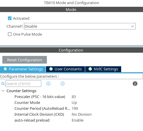
Firstly configure some timer (we use TIM10 here):
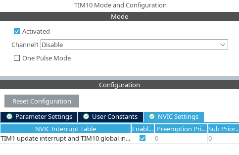
We also need to enable the global timer 10 interrupt:
Implementation
We use bitbanding to address the bit used for GPIO:
// The led_bb_bit points to the bitband address for controlling the PC13
uint8_t *led_bb_bit = (uint8_t*) BITBAND_BIT_ADDR(&LED_GPIO_Port->ODR, 13);
A few more global variables keep track of the counter and pwm value:
// Variables to run the pwm.  led_pwm_cnt goes from 0-255 and then roll back over to 0.
// led_pwm_val determines the ratio between on and off status of the LED.
uint32_t led_pwm_cnt;
uint8_t led_pwm_val = 0x00;
Now the actual PWM work can be handled in the interrupt callback:
// Callback which runs the PWM
void HAL_TIM_PeriodElapsedCallback(TIM_HandleTypeDef *htim) {

    if (htim->Instance == LED_PWM_TIM) {

        // Increase the counter - it will roll over automatically every 256 bit
        ++led_pwm_cnt;

        // Switch LED on off or on depending on value of led_pwm_cnt.
        *led_bb_bit = (uint8_t) led_pwm_cnt >= led_pwm_val ? 1 : 0;

    }

}
Using BSRR
After implementing the bit banging using bit-banding, I came to realize that this could also be implemented simply by using the BSRR register:
void HAL_TIM_PeriodElapsedCallback(TIM_HandleTypeDef *htim) {

    if (htim->Instance == LED_PWM_TIM) {
        ++led_pwm_cnt; // The counter is 8 bit so will wrap around after 255

        // Use BSRR to set or reset bit 13 of the LED GPIO port
        LED_GPIO_Port->BSRR = led_pwm_cnt >= led_pwm_val ? GPIO_BSRR_BS13 : GPIO_BSRR_BR13;
    }

}
The GPIO_BSRR_BS13 and GPIO_BSRR_BR13 macros, contain a formula which calculates the values, but as these are most likely optimized by the compiler into constants, this is likely to perform just as well as the bit-banding approach.

