Difference between revisions of "STM32 I²C LCD"
| (3 intermediate revisions by the same user not shown) | |||
| Line 12: | Line 12: | ||
[[File:I2C extender on LCD display.webp|600px]] | [[File:I2C extender on LCD display.webp|600px]] | ||
| + | |||
| + | The [[I²C]] extender is connected in the following way: | ||
| + | |||
| + | [[File:I2c Module to LCD.png|1000px]] | ||
| + | |||
| + | In other words, the 8 bits of the GPIO extender is mapped as follows: | ||
| + | |||
| + | {| class=wikitable | ||
| + | |- | ||
| + | ! Name | ||
| + | ! Function | ||
| + | ! Description | ||
| + | |- | ||
| + | | P7 | ||
| + | | D7 | ||
| + | | MSB of data | ||
| + | |- | ||
| + | | P6 | ||
| + | | D6 | ||
| + | | | ||
| + | |- | ||
| + | | P5 | ||
| + | | D5 | ||
| + | | | ||
| + | |- | ||
| + | | P4 | ||
| + | | D4 | ||
| + | | | ||
| + | |- | ||
| + | | P3 | ||
| + | | BT | ||
| + | | Backlight control | ||
| + | |- | ||
| + | | P2 | ||
| + | | E | ||
| + | | Enable pin | ||
| + | |- | ||
| + | | P1 | ||
| + | | RW | ||
| + | | Read/write toggle | ||
| + | |- | ||
| + | | P0 | ||
| + | | RS | ||
| + | | | ||
| + | |} | ||
== Miscellaneous Links == | == Miscellaneous Links == | ||
| Line 18: | Line 63: | ||
* [https://github.com/fdebrabander/Arduino-LiquidCrystal-I2C-library Arduino library used for inspiration] | * [https://github.com/fdebrabander/Arduino-LiquidCrystal-I2C-library Arduino library used for inspiration] | ||
* [https://github.com/blackhack/LCD_I2C/blob/master/src/LCD_I2C.cpp Another Arduino library] | * [https://github.com/blackhack/LCD_I2C/blob/master/src/LCD_I2C.cpp Another Arduino library] | ||
| + | * [https://github.com/taburyak/LCD1602_I2C_OR_4BIT_STM32 STM32 Code] | ||
Latest revision as of 02:41, 16 June 2022
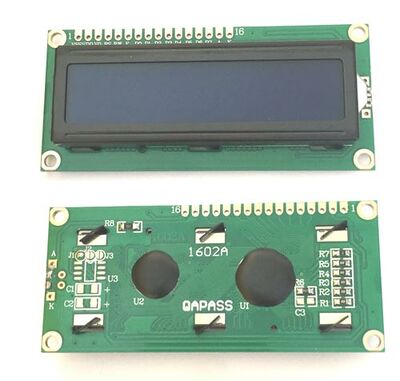
LCD Display modules are readily available and they are dirt cheap (< $2 typically). They come in different "resolutions" typically expressed as number of characters and number of lines. Common ones are 1602 (16 characters in 2 lines) and 2004 (20 characters in 4 lines).
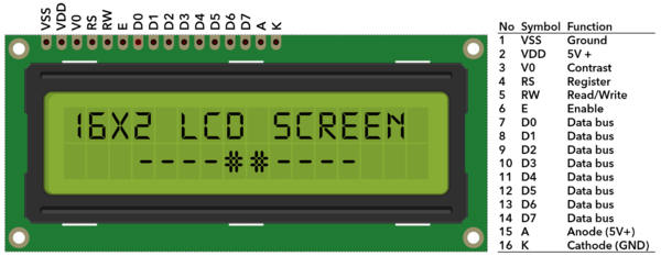
The modules are interfaces by an 8 bit parallel data bus (can be operated in 4 bit mode) and some control signals:
These can of course be "driven" by an STM32 by interfacing these pins directly, but at a minimum that would tie up 8 GPIO pins for one display.
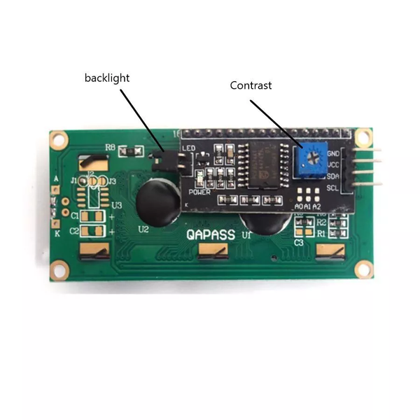
To cut down on the number of pins needed a GPIO extender can be used and because this approach is quite a lot easier a lot of the LCD modules come with an I²C GPIO extender already attached.
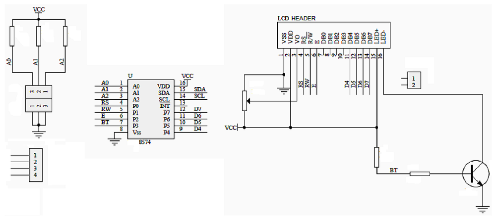
The I²C extender is connected in the following way:
In other words, the 8 bits of the GPIO extender is mapped as follows:
| Name | Function | Description |
|---|---|---|
| P7 | D7 | MSB of data |
| P6 | D6 | |
| P5 | D5 | |
| P4 | D4 | |
| P3 | BT | Backlight control |
| P2 | E | Enable pin |
| P1 | RW | Read/write toggle |
| P0 | RS |


