Difference between revisions of "DIY STM32 Programmer (ST-Link/V2-1)"
| Line 1: | Line 1: | ||
[[Category:STM32]][[Category:STM32 Projects]][[Category:Work in progress]]{{metadesc|DIY ST-Link V2.1}} | [[Category:STM32]][[Category:STM32 Projects]][[Category:Work in progress]]{{metadesc|DIY ST-Link V2.1}} | ||
| + | [[File:STLink.jpg|thumb|Original ST-Link]] | ||
[[ST-Link]] devices are almost essential when developing software for the [[STM32]] [[MCU]]s. They are relatively cheap and easily available. | [[ST-Link]] devices are almost essential when developing software for the [[STM32]] [[MCU]]s. They are relatively cheap and easily available. | ||
| − | |||
They roughly fall into two different categories. [[ST]] themselves make a number of them and they all work quite well. | They roughly fall into two different categories. [[ST]] themselves make a number of them and they all work quite well. | ||
Revision as of 01:57, 13 July 2021
ST-Link devices are almost essential when developing software for the STM32 MCUs. They are relatively cheap and easily available.
They roughly fall into two different categories. ST themselves make a number of them and they all work quite well.
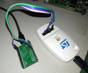
One thing that annoys me with the original ST-Link devices is that the programming header is unlabelled. This essentially mean that every time I use it I have to Google for the actual pinout.
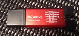
There are also a lot of Chinese clones available and while they have some limitations they also work quite well.
Original ST-Link V2.1
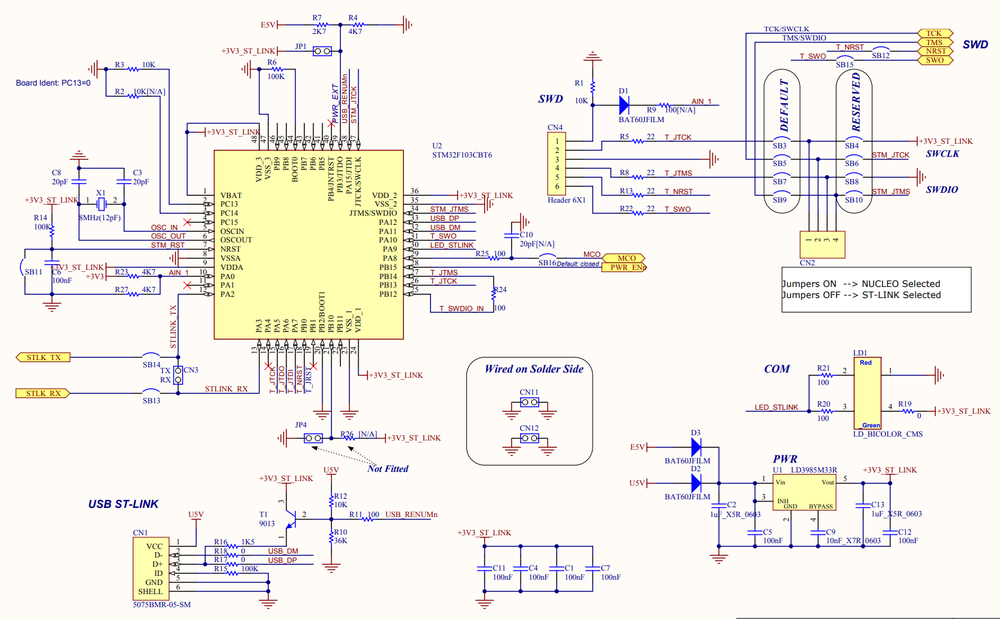
The schematic of the original ST-Link is readily available
Schematics
Based on ST's original schematics, creating a version using only parts from JLCPCB's parts library was easy.
One thing I left out was the serial resistors of the programming header. This might very well come back and bite me in the ass but space is going to be at a premium.
PCB
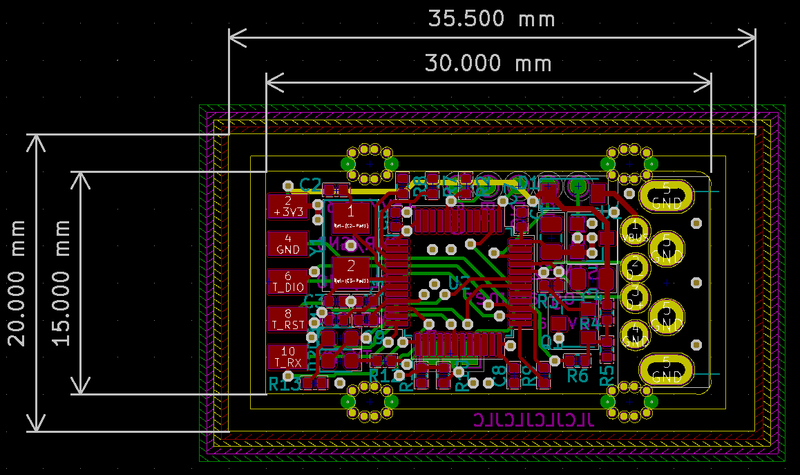
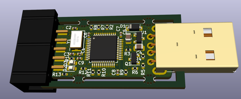
The final rev. a layout looks like this:
The KiCAD 3D model:
